
 EN
EN
Transmit/receive modules, commonly known as T/R modules, are among the most important building blocks in modern radar, phased-array communication, electronic countermeasure, satellite communication, and other advanced radio-frequency systems. Each module must transmit a high-power RF signal, receive a much weaker reflected or incoming signal, and maintain reliable isolation between the two operating paths.
Within this compact and demanding RF environment, the microwave ceramic filter performs a role that is easy to underestimate. It is not simply a component that removes unwanted frequencies. A properly designed ceramic filter helps protect sensitive receiving circuits, improves transmitted signal purity, reduces interference, supports channel selectivity, and contributes to the overall size, stability, and reliability of the T/R module.
Understanding the Signal Path Inside a T/R Module
A typical T/R module includes a transmit chain, a receive chain, switching or duplexing circuitry, control electronics, and an antenna interface.
In transmit mode, the RF signal passes through amplification stages before being delivered to the antenna. The module must ensure that the transmitted energy remains within the intended operating band and that harmonics, spurious signals, and out-of-band noise are adequately suppressed.
In receive mode, the situation is even more sensitive. The useful signal arriving at the antenna may be extremely weak. Before it reaches the low-noise amplifier and subsequent receiver stages, unwanted signals should be rejected as early as possible. Otherwise, strong out-of-band energy may overload the receiver, reduce sensitivity, generate intermodulation products, or mask the desired signal.
Microwave ceramic filters can be positioned at different points in these paths, depending on the system architecture. They may be installed before or after an amplifier, integrated near the antenna port, or combined with other filtering and duplexing functions. Their exact placement is determined by frequency, power level, insertion-loss requirements, rejection targets, thermal conditions, and available space.
1. Selecting the Required Operating Band
The first and most direct function of a microwave ceramic filter is frequency selection. It allows signals within a specified passband to travel through the module while attenuating frequencies outside that band.
In radar and communication systems, the electromagnetic environment is rarely clean. Nearby transmitters, adjacent channels, local oscillators, switching electronics, and other RF subsystems may all generate unwanted energy. Without sufficient filtering, this energy can enter the signal chain and affect system performance.
A ceramic band-pass filter establishes a controlled spectral window for the T/R module. Its center frequency, bandwidth, passband ripple, insertion loss, return loss, and out-of-band attenuation can be designed around the application.
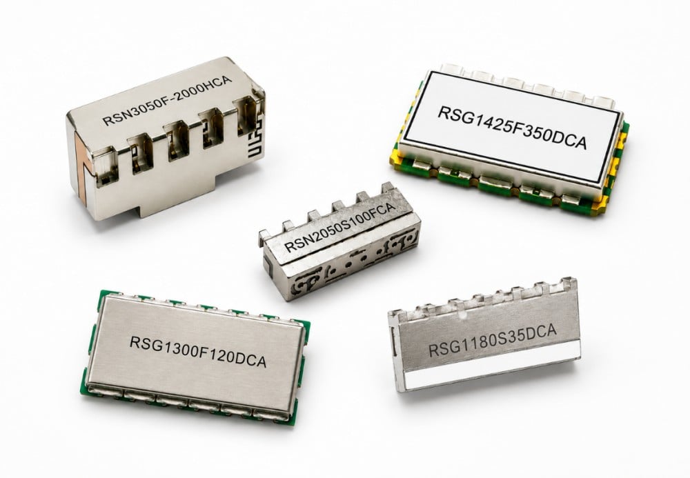
RSWave microwave dielectric ceramic filters use high-dielectric-constant, low-loss, and temperature-stable ceramic materials as the resonant medium. The company’s published product range includes standard and customizable filters from approximately 400 MHz to 7 GHz, covering narrowband and broadband requirements for wireless communication, navigation, radar, satellite communication, and other RF front-end applications.
2. Protecting the Sensitive Receive Chain
The receive channel is often the most vulnerable section of a T/R module. A low-noise amplifier is designed to detect weak signals, but it can also be affected by strong unwanted signals outside the operating band.
A ceramic filter placed near the receiver input provides preselection before unwanted energy reaches the low-noise amplifier. This helps reduce the risk of receiver desensitization, compression, and interference.
For example, a radar receiver may need to detect a faint echo shortly after the transmitter has emitted a high-power pulse. Although the T/R switch provides isolation, residual leakage, nearby transmitters, and broadband noise can still reach the receive path. A filter with appropriate rejection characteristics adds another layer of frequency-selective protection.
This is especially valuable in dense electromagnetic environments, such as multifunction radar platforms, unmanned systems, communication base stations, electronic countermeasure equipment, and satellite terminals.
However, receiver protection cannot be considered separately from insertion loss. Every fraction of a decibel lost before the low-noise amplifier can influence the receiver noise figure. Filter selection therefore requires a practical balance between low passband loss and strong out-of-band rejection.
3. Improving Transmitted Signal Purity
A power amplifier does not produce only the desired carrier. Depending on its operating point, modulation, linearity, and surrounding circuitry, it may also generate harmonics, broadband noise, and spurious emissions.
A microwave ceramic filter in the transmit path suppresses unwanted frequency components before the signal reaches the antenna. This helps the T/R module comply with spectral requirements and reduces the possibility of interfering with adjacent channels or other onboard RF systems.
Improved transmitted signal purity is particularly important in active electronically scanned arrays. Hundreds or even thousands of T/R modules may operate together. Small imperfections at the module level can accumulate and influence the spectral performance of the complete array.
The filter must nevertheless be selected with sufficient power-handling capability. High average power, pulse power, thermal cycling, impedance mismatch, and installation conditions can all influence long-term performance. The final design should therefore be verified under the module’s actual power and temperature conditions rather than evaluated only at low signal levels.
4. Increasing Isolation Between Transmit and Receive Functions
T/R modules require effective separation between high-power transmission and high-sensitivity reception. This separation is normally achieved through switches, circulators, duplexers, or other routing components, but frequency-selective devices can provide additional isolation.
When the transmit and receive channels operate at different frequencies, a microwave dielectric ceramic duplexer can integrate two filtering paths into one compact component. One branch passes the transmit band, while the other passes the receive band. Both branches can share a common antenna port while maintaining isolation between the channels.
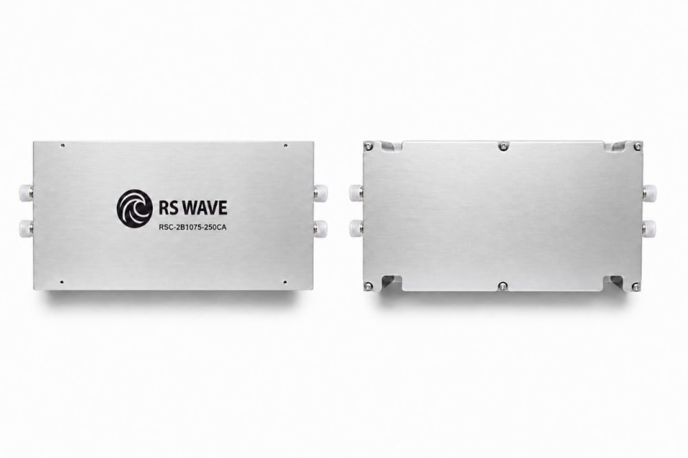
RSWave’s microwave dielectric ceramic duplexers are based on high-Q, low-loss ceramic resonators and cover approximately 400 MHz to 6 GHz. Their compact structure, temperature stability, and surface-mount compatibility make them relevant to integrated RF front-end designs in which PCB area and weight are limited.
For systems using the same frequency in alternating time slots, a separate filter and RF switch arrangement may be more appropriate. For frequency-division systems, an integrated duplexer can reduce the number of discrete components and simplify the antenna interface.
5. Supporting Miniaturization of the RF Front End
Modern phased-array and portable RF platforms place strict limits on module dimensions. Element spacing in an antenna array is related to wavelength, so the electronics behind each radiating element must often fit into a tightly controlled physical area.
Microwave dielectric ceramics have a high relative permittivity. This allows resonant structures to be made smaller than many equivalent air-filled or conventional metallic resonators operating at the same frequency. As a result, ceramic filters can provide useful selectivity in a compact and lightweight format.
Miniaturization is not only a mechanical advantage. Shorter interconnections can reduce parasitic effects, simplify RF routing, and support higher levels of integration. Smaller components may also help designers place the filter closer to the device it is intended to protect.
The smallest filter, however, is not automatically the best filter. Designers must also consider unloaded Q, conductor loss, coupling structure, heat dissipation, manufacturing tolerance, PCB layout, shielding, and rejection performance. A practical filter is the one that meets the complete electrical and environmental specification within the available volume.
6. Maintaining Frequency Stability Across Temperature
T/R modules may operate in outdoor base stations, airborne systems, vehicles, ships, satellites, industrial equipment, or other environments where temperature can change significantly.
If a filter’s resonant frequency shifts too far with temperature, the passband may move away from the required channel. This can increase insertion loss, distort the signal, or reduce rejection at critical frequencies.
Temperature-stable microwave ceramic materials help limit this drift. Material formulation, resonator geometry, metallization, coupling design, mounting method, and surrounding PCB structure all affect the final temperature response.
For demanding applications, engineers should evaluate more than a room-temperature network-analyzer plot. Measurements should cover the expected operating-temperature range and, where applicable, vibration, humidity, power cycling, and long-term aging.
7. Improving System-Level Reliability
The value of a microwave ceramic filter should be judged at the module and system levels, not only as an individual S-parameter component.
A suitable filter can contribute to:
- Better receiver sensitivity in the presence of interference
- Lower risk of low-noise amplifier overload
- Reduced harmonic and spurious emissions
- Improved transmit-to-receive isolation
- More consistent performance across temperature
- Smaller and lighter RF front-end assemblies
- Easier integration of filtering and duplexing functions
These benefits can improve detection range, communication quality, electromagnetic compatibility, and operational reliability. Their actual impact depends on the complete RF budget, including amplifier gain, noise figure, switch isolation, antenna matching, transmission-line loss, and shielding.
Key Parameters When Selecting a Ceramic Filter for a T/R Module
Engineers should begin with a clear electrical and mechanical specification. Important parameters include:
- Center frequency and bandwidth: The filter must pass the complete operational signal, including modulation bandwidth, frequency tolerance, and expected temperature drift.
- Insertion loss: Low loss is particularly important before the low-noise amplifier and after the power amplifier.
- Out-of-band rejection: Rejection should be defined at specific interfering frequencies rather than described only as a general maximum value.
- Return loss or VSWR: Good impedance matching helps reduce reflections and supports predictable amplifier and antenna performance.
- Power handling: Transmit-path filters must tolerate the required continuous-wave or pulsed power, including mismatch conditions.
- Temperature stability: Frequency shift and loss variation should remain acceptable across the specified environment.
- Size and mounting method: The package should suit the available PCB area, assembly process, grounding structure, and thermal design.
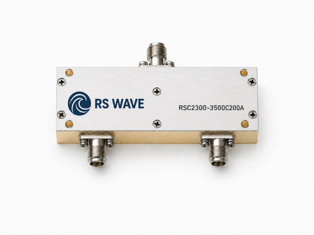
- Customization capability: Many T/R modules use non-standard frequencies, bandwidths, attenuation points, or package dimensions. A customized filter may achieve a better system-level trade-off than a general-purpose catalog component.
Working With an Experienced Microwave Ceramic Component Supplier
A T/R module filter should ideally be developed through communication between the module designer and the component manufacturer. Useful design inputs include the required passband, rejection frequencies, source and load impedance, power level, temperature range, mechanical envelope, interface format, and expected annual quantity.
Jiaxing Ruishang Electronic Technology Co., Ltd. has focused on the research, development, production, and sale of microwave ceramic components since 2015. Its product portfolio includes microwave dielectric ceramic filters, ceramic duplexers, LC filters, cavity filters, and ceramic antennas. The company also provides simulation
Table of Contents
- Understanding the Signal Path Inside a T/R Module
- 1. Selecting the Required Operating Band
- 2. Protecting the Sensitive Receive Chain
- 3. Improving Transmitted Signal Purity
- 4. Increasing Isolation Between Transmit and Receive Functions
- 5. Supporting Miniaturization of the RF Front End
- 6. Maintaining Frequency Stability Across Temperature
- 7. Improving System-Level Reliability
- Key Parameters When Selecting a Ceramic Filter for a T/R Module
- Working With an Experienced Microwave Ceramic Component Supplier