
 EN
EN
RF power amplifiers increase the power of a wanted radio-frequency signal, but no practical amplifier is perfectly linear. When a transistor is driven near compression, its nonlinear behavior generates harmonics at integer multiples of the fundamental frequency. A transmitter operating at 100 MHz, for example, may produce unwanted energy at 200 MHz, 300 MHz, and higher frequencies. If those harmonics reach the antenna, they can cause electromagnetic interference, violate emission limits, reduce spectral efficiency, and disturb nearby receivers.
An LC low-pass filter is one of the most practical solutions. Built from inductors and capacitors, it passes the required fundamental frequency while attenuating signals above its cutoff frequency. In RF modules, radio transmitters, telemetry equipment, radar subsystems, satellite terminals, test instruments, and customized wireless platforms, the filter is commonly installed directly after the RF power amplifier.
Why RF Power Amplifiers Generate Harmonics
A perfectly linear amplifier would reproduce the input waveform at a higher power without changing its shape. Real RF devices, however, exhibit nonlinear gain, junction capacitance, bias variation, and saturation. As output power rises, the waveform becomes distorted, and that distortion appears in the frequency domain as harmonics.
The second harmonic occurs at twice the carrier frequency, the third at three times the carrier frequency, and so on. Their levels depend on transistor technology, amplifier class, bias point, output power, impedance matching, and modulation. Switching or highly compressed amplifiers can deliver high efficiency, but they usually require stronger harmonic filtering.
Harmonics can also create false responses in measurement systems, couple into navigation or communication channels, and increase stress on downstream components. Harmonic suppression should therefore be treated as part of the amplifier output design.
How an LC Low-Pass Filter Works
An LC low-pass filter uses the opposite frequency behavior of inductors and capacitors. Inductive reactance rises with frequency:
XL = 2πfL
Capacitive reactance falls as frequency rises:
XC = 1/(2πfC)
In a typical topology, series inductors impede high-frequency harmonic current, while shunt capacitors provide a low-impedance path that diverts unwanted energy toward ground. At the fundamental frequency, the values are selected to keep insertion loss low so the amplifier can transfer power efficiently to the load.
Above the cutoff frequency, attenuation increases according to the number of reactive sections and the selected filter response. A higher-order network provides a steeper transition when the first unwanted harmonic is relatively close to the required passband.
Choosing the Cutoff Frequency
The cutoff frequency must be high enough to pass the wanted signal and its modulation bandwidth, but low enough to attenuate the lowest important harmonic. For a narrowband 100 MHz carrier, the cutoff may be placed above the occupied channel bandwidth and well below the 200 MHz second harmonic.
For modulated systems, designers must consider the full occupied bandwidth, spectral mask, production frequency tolerance, and temperature drift. A cutoff placed too close to the wanted band can distort the signal envelope, degrade error vector magnitude, and increase reflected power. A cutoff placed too high may provide insufficient harmonic rejection.
Important filter-design inputs include:
- Fundamental operating frequency
- Occupied signal bandwidth
- Maximum RF output power
- Required second- and third-harmonic attenuation
- Maximum acceptable insertion loss
- Source and load impedance
- Operating temperature range
- Package dimensions
- Connector, surface-mount, or through-hole interface
These parameters should be defined before selecting a standard filter or developing a customized LC network.
Filter Order and Response
Filter order determines how rapidly attenuation increases beyond the cutoff frequency. Each additional reactive component can improve roll-off, but it also introduces additional loss, tolerance sensitivity, cost, and PCB layout complexity.
A Butterworth response provides a maximally flat passband and is useful when passband amplitude consistency is important. A Chebyshev response offers a steeper transition for a given filter order but introduces controlled passband ripple. An elliptic response can create transmission zeros and extremely sharp rejection, although it is more sensitive to component tolerances and parasitic effects.
For RF power-amplifier harmonic suppression, the best solution is not automatically the highest-order network. The optimum design balances harmonic rejection, insertion loss, voltage stress, current handling, manufacturability, physical size, and amplifier stability.
In many practical transmitters, a three- to seven-pole LC low-pass filter provides an effective compromise between rejection performance and implementation complexity.
Power Handling, Q Factor, and Component Selection
Small-signal filter calculations are only the beginning. At the output of an RF power amplifier, inductors and capacitors may be exposed to substantial RF current and voltage. Components with insufficient ratings can heat, detune, saturate, crack, or fail.
Inductor Q factor strongly influences insertion loss. A higher-Q inductor stores energy with lower resistive loss, helping maintain transmitter efficiency. Capacitors should provide low equivalent series resistance, stable capacitance, suitable RF dielectric characteristics, and adequate voltage margin.
The voltage rating must account for impedance mismatch and standing waves rather than only the nominal 50-ohm operating condition. Under a poor antenna match, peak RF voltage inside the filter may be considerably higher than expected.
Component tolerance is another important factor. Variations in inductance and capacitance can shift the cutoff frequency and harmonic rejection points. Temperature drift, PCB parasitics, solder-pad capacitance, trace inductance, and enclosure effects can further change the measured response.
For compact filters operating at higher frequencies, electromagnetic simulation and tolerance analysis are essential for ensuring that production units meet the target specifications.
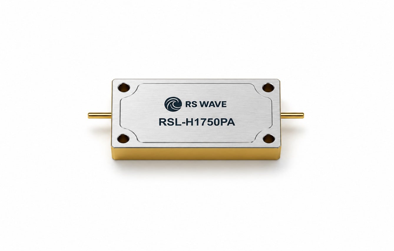
RSWave supplies RF LC filters in low-pass, high-pass, band-pass, and band-stop configurations. Its product range supports compact surface-mount and through-hole structures, while customized frequency, attenuation, package, and interface requirements can be developed for specialized RF systems.
PCB Layout and Grounding
At RF frequencies, the PCB and housing become part of the filter circuit. Long traces add unwanted inductance, component pads introduce capacitance, and poor grounding can significantly reduce stopband attenuation.
The LC filter should be installed as close as practical to the power-amplifier output. Interconnections should be short, controlled in impedance, and referenced to a continuous ground plane.
Shunt capacitors require low-inductance ground paths. Multiple grounding vias should be positioned close to each capacitor pad so high-frequency current can return efficiently. A long path between a capacitor and ground may prevent the component from providing the expected harmonic attenuation.
Input and output traces should also be physically separated. When they are routed close together, electromagnetic coupling may allow harmonic energy to bypass the filter network. In compact or high-power modules, a grounded metal enclosure or internal shielding partition may be required.
Although an LC filter is passive, its insertion loss converts part of the RF power into heat. Sufficient copper area, airflow, thermal contact, and housing design help maintain stable filter performance.
Impedance Matching and Amplifier Stability
The low-pass filter must operate together with the amplifier output matching network. A filter designed for nominal 50-ohm source and load impedances may present a reactive impedance outside the passband. The impedance seen by the transistor should therefore be evaluated over a wide frequency range.
At harmonic frequencies, load impedance can influence amplifier efficiency, drain or collector voltage swing, and transistor reliability. In some systems, the low-pass filter is integrated into the output matching network so it performs both impedance transformation and harmonic suppression.
This integrated approach can reduce component count and module size, but it normally requires accurate transistor models, load-pull data, and harmonic-balance simulation.
A vector network analyzer can verify filter insertion loss, return loss, cutoff frequency, and stopband rejection before full-power testing. Harmonic emissions can then be measured with a spectrum analyzer, directional coupler, suitable RF attenuation, and a properly rated dummy load.
Testing should cover minimum and maximum supply voltages, temperature extremes, different output-power settings, production component tolerances, and representative antenna mismatch conditions.
How Much Harmonic Suppression Is Possible?
The final suppression level depends on the amplifier’s original harmonic output and the filter attenuation at each harmonic frequency.
For example, assume that an amplifier produces a second harmonic at −25 dBc. If the LC low-pass filter provides 35 dB of attenuation at the second-harmonic frequency, the theoretical filtered result may approach −60 dBc.
Actual measurements may differ because of connector coupling, PCB radiation, inadequate grounding, component self-resonance, enclosure leakage, and measurement uncertainty.
A technically correct circuit schematic can still deliver poor harmonic suppression when its physical implementation is not designed according to RF principles. This is one reason why simulation, PCB design, enclosure design, and laboratory validation should be treated as a single engineering process.
For more demanding systems, an LC low-pass filter may be combined with a cavity filter, ceramic filter, or distributed transmission-line structure. LC filters are attractive because of their compact size, integration flexibility, and cost efficiency. Cavity filters can provide high Q factor, low insertion loss, strong out-of-band rejection, and greater power-handling capability in many medium- and high-frequency applications.
Selecting a Custom LC Low-Pass Filter
A customized LC filter is often preferable when an off-the-shelf component cannot meet the required frequency, package, rejection, or power target.
When requesting a custom filter, engineers should provide:
- Required passband
- Desired cutoff or transition region
- Second- and third-harmonic frequencies
- Maximum passband insertion loss
- Return-loss or VSWR requirement
- Stopband attenuation targets
- Maximum continuous and peak RF power
- Operating temperature range
- Mechanical dimensions
- Connector or pin configuration
- Environmental and reliability requirements
Providing complete specifications allows the filter manufacturer to select a suitable topology, component technology, housing structure, and manufacturing process.
RSWave’s RF component portfolio includes LC filters, cavity filters, microwave dielectric ceramic filters, duplexers, multiplexers, and antennas. These products are used in communication infrastructure, radar detection, satellite communication, navigation equipment, unmanned systems, aerospace modules, industrial RF electronics, and customized microwave platforms.
Conclusion
An LC low-pass filter suppresses RF power-amplifier harmonics by combining series inductance and shunt capacitance to pass the fundamental signal while rejecting higher-frequency energy.
Effective harmonic suppression depends on much more than choosing a cutoff frequency. Filter order, response type, component Q factor, power rating, impedance behavior, grounding, shielding, thermal management, PCB layout, and production tolerance all influence real-world performance.
When these factors are addressed together, a properly engineered LC low-pass filter can significantly reduce second- and third-harmonic emissions, improve electromagnetic compatibility, protect nearby receivers, and help an RF transmitter satisfy its spectral requirements.
For applications requiring a compact package, low insertion loss, defined harmonic rejection, high reliability, or a nonstandard interface, a customized RF LC filter provides a practical route from circuit design to production-ready RF performance.
Table of Contents
- Why RF Power Amplifiers Generate Harmonics
- How an LC Low-Pass Filter Works
- Choosing the Cutoff Frequency
- Filter Order and Response
- Power Handling, Q Factor, and Component Selection
- PCB Layout and Grounding
- Impedance Matching and Amplifier Stability
- How Much Harmonic Suppression Is Possible?
- Selecting a Custom LC Low-Pass Filter
- Conclusion