
 EN
EN
In modern wireless communication systems, RF signals are becoming increasingly complex due to the rapid development of 5G networks, satellite communication, radar systems, automotive electronics, and IoT devices. Maintaining signal purity and reducing unwanted interference have become critical challenges in RF circuit design. Among various passive RF components, the RF LC filter plays an essential role in signal conditioning by allowing specific frequency bands to pass while suppressing unwanted signals.
Jiaxing Ruishang Electronic Technology Co., Ltd. (RSWave) specializes in RF microwave components, including RF LC filters, cavity filters, ceramic filters, duplexers, and antenna solutions. Its RF LC filter products are designed for applications requiring compact size, stable performance, and customized frequency responses, covering frequency ranges from DC to high-frequency microwave applications.
1. What Is an RF LC Filter?
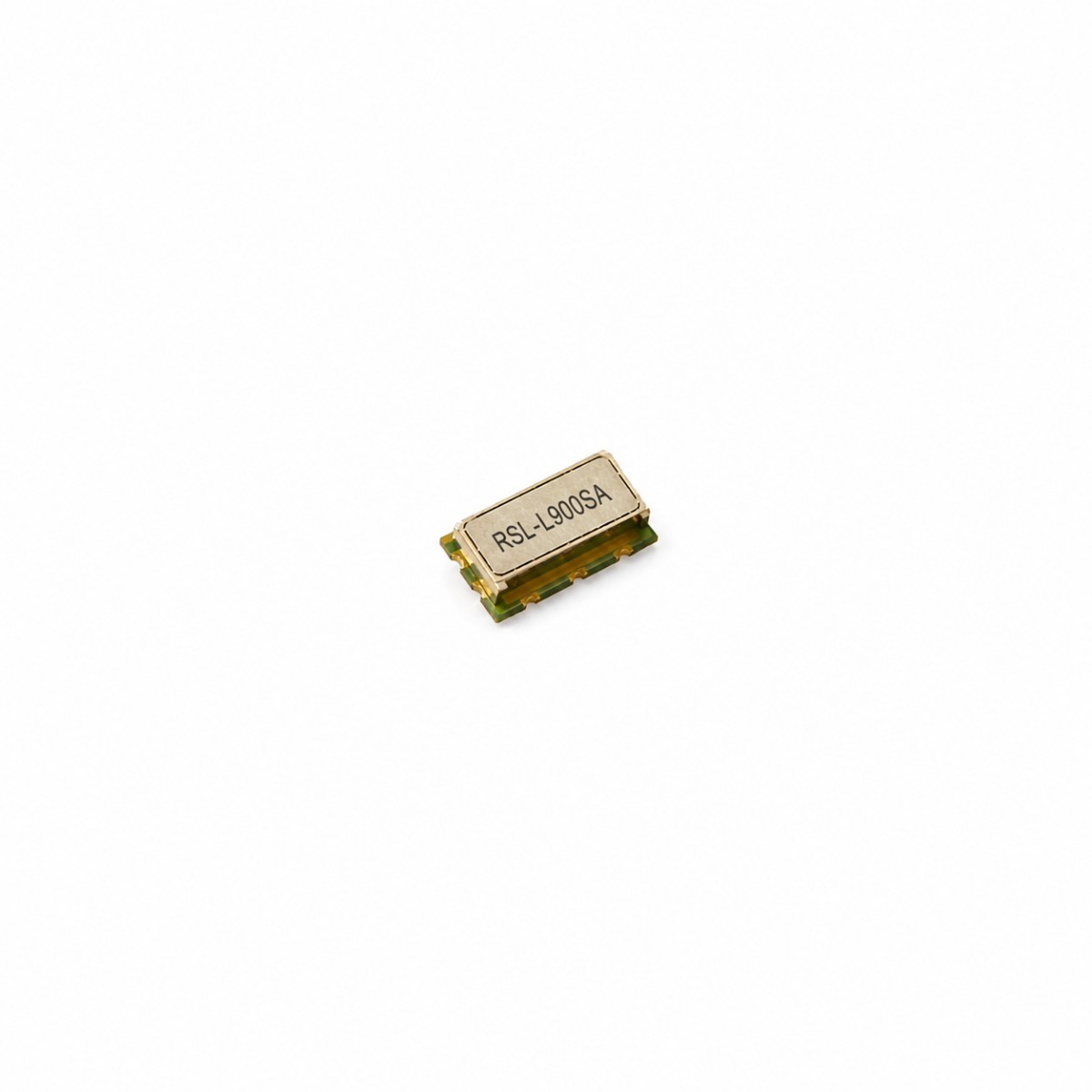
An RF LC filter is a passive frequency-selective circuit consisting mainly of inductors (L) and capacitors (C). The working principle is based on the different impedance characteristics of inductive and capacitive components at different frequencies.
An inductor has low impedance at low frequencies and increasing impedance at high frequencies, while a capacitor behaves in the opposite way, offering high impedance at low frequencies and low impedance at high frequencies. By combining inductors and capacitors in specific circuit configurations, engineers can create filters that selectively control signal transmission.
The primary function of an RF LC filter is to:
Remove unwanted harmonic signals and noise;
Improve receiver sensitivity by reducing interference;
Protect RF components from out-of-band signals;
Improve overall system communication reliability.
Unlike active filters that require power supplies and amplification circuits, RF LC filters are passive devices. They provide excellent reliability, low insertion loss, compact structure, and long operational life, making them widely used in wireless communication and microwave systems.
2. Working Principle of RF LC Filters
The operation of an RF LC filter depends on resonance characteristics between inductors and capacitors.
The basic resonance frequency can be calculated using:
f₀ = 1 / (2π√LC)
where:
f₀ represents the resonant frequency;
L represents inductance;
C represents capacitance.
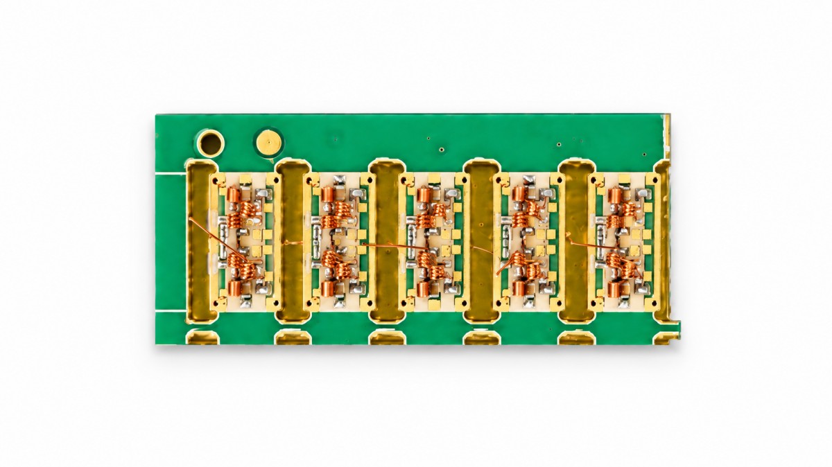
At the designed resonant frequency, the energy exchange between the magnetic field of the inductor and the electric field of the capacitor creates a selective filtering effect.
For example, in a band-pass LC filter, signals near the target frequency experience low impedance and can pass through efficiently. Signals outside the desired frequency range encounter higher impedance and are significantly attenuated.
This frequency-selective characteristic makes RF LC filters especially valuable in RF front-end circuits, where maintaining a clean signal path is essential.
RSWave’s RF LC filter solutions include different structures such as low-pass filters, high-pass filters, band-pass filters, and band-stop filters, allowing engineers to select suitable designs according to frequency requirements and application environments.
3. Typical Circuit Structures of RF LC Filters
Different RF systems require different filtering characteristics. Therefore, LC filters can be designed into several common circuit structures.
3.1 Low-Pass LC Filter
A low-pass LC filter allows signals below a certain cutoff frequency to pass while reducing higher-frequency components.
A typical structure consists of:
A series inductor connected in the signal path;
A shunt capacitor connected to ground.
At low frequencies, the inductor presents relatively low impedance, allowing signals to pass. At high frequencies, the inductor impedance increases and the capacitor provides a path for unwanted high-frequency signals to ground.
Low-pass LC filters are commonly used in:
RF power supply filtering;
Harmonic suppression circuits;
Transmitter output stages.
3.2 High-Pass LC Filter
A high-pass LC filter works in the opposite way. It blocks low-frequency signals while allowing high-frequency signals to pass.
The typical structure includes:
A series capacitor;
A shunt inductor.
At low frequencies, the capacitor blocks signal transmission. As frequency increases, capacitor impedance decreases, allowing RF signals to pass.
High-pass filters are often applied in:
Receiver front-end circuits;
Interference suppression systems;
Microwave communication modules.
3.3 Band-Pass LC Filter
Band-pass LC filters are among the most widely used RF filters because most communication systems operate within specific frequency bands.
A band-pass structure combines high-pass and low-pass characteristics, allowing only signals within a defined frequency range to pass.
Typical applications include:
5G base stations;
RF remote radio units (RRU);
Satellite communication terminals;
Radar systems
The center frequency, bandwidth, insertion loss, and rejection performance can be customized according to system requirements. RSWave provides customized RF LC filter solutions using advanced simulation and design capabilities to meet different customer specifications.
3.4 Band-Stop or Notch LC Filter
A band-stop filter suppresses signals within a specific frequency range while allowing frequencies outside that range to pass.
These filters are commonly used to eliminate:
Electromagnetic interference;
Specific unwanted communication channels;
Harmonic interference.
For example, in complex RF environments, notch filtering can prevent strong interference signals from affecting receiver performance.
4. Key Performance Parameters of RF LC Filters
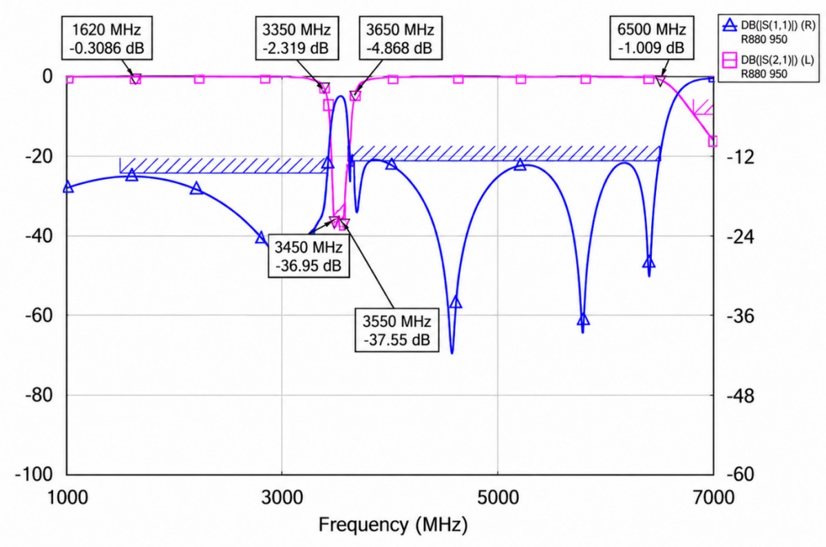
When selecting an RF LC filter, engineers usually evaluate several important technical parameters.
Insertion Loss
Insertion loss indicates the signal power reduction after passing through the filter. Lower insertion loss means better transmission efficiency.
Bandwidth
Bandwidth defines the frequency range where the filter allows signals to pass effectively. Different communication standards require different bandwidth designs.
Return Loss and VSWR
Good impedance matching is critical in RF systems. Low VSWR and good return loss help minimize signal reflection and improve system efficiency.
Attenuation Performance
Attenuation describes how effectively the filter suppresses unwanted frequencies. High attenuation outside the passband improves signal isolation.
Size and Integration Capability
Modern RF equipment requires smaller and lighter components. Compact LC filter designs enable easier integration into communication modules and portable devices.
5. Applications of RF LC Filters in Modern Industries
With the expansion of wireless technologies, RF LC filters are used across many industries.
5G and Wireless Communication
In 5G infrastructure, RF filters help separate frequency channels, reduce interference, and improve network stability. Base stations and RF modules rely on high-performance filtering components to maintain reliable communication.
Satellite Communication and Aerospace
Satellite systems require stable signal transmission under challenging environments. RF LC filters help protect communication links by suppressing unwanted frequency components.
Radar and Defense Electronics
Radar systems require extremely accurate frequency control. RF filters improve target detection capability by reducing noise and interference.
Automotive and Navigation Systems
Modern vehicles integrate multiple wireless technologies, including GNSS, vehicle communication, and wireless connectivity. RF filters help maintain signal accuracy and prevent interference between different systems.
6. Why Choose Customized RF LC Filter Solutions?
Standard filters may not always satisfy specific system requirements. Customized RF LC filters allow engineers to optimize:
Center frequency;
Bandwidth;
Filter topology;
Mechanical dimensions;
Connector configuration;
Environmental performance.
As an RF component manufacturer, RSWave provides customized design support based on customer application requirements. Its engineering team focuses on simulation analysis, performance optimization, and production consistency to help customers achieve reliable RF system integration.
Conclusion
RF LC filters are fundamental components in modern RF and microwave systems. Through the interaction between inductors and capacitors, they provide precise frequency selection, interference reduction, and signal protection.
From simple low-pass structures to advanced band-pass and customized filtering solutions, LC filter technology continues to support the development of communication networks, radar systems, satellite links, and intelligent electronic devices.
For companies developing RF modules, wireless communication equipment, or microwave systems, selecting a reliable RF LC filter manufacturer with strong design capability and customization experience is essential for achieving stable and high-performance products. Jiaxing Ruishang Electronic Technology Co., Ltd. continues to provide RF filter solutions designed for demanding communication environments and next-generation electronic applications.