
 EN
EN
The rapid deployment of Low Earth Orbit (LEO) satellite constellations, most notably SpaceX’s Starlink, has fundamentally transformed the global telecommunications landscape. By positioning thousands of satellites in orbits ranging from 340 to 600 kilometers above the Earth, LEO networks deliver high-speed, low-latency broadband internet to remote and underserved regions worldwide. However, this massive leap in connectivity comes with a significant technological challenge: electromagnetic spectrum congestion.
As the sky fills with active transmitters operating across overlapping frequency bands, maintaining signal integrity becomes incredibly difficult. In this complex electromagnetic environment, Radio Frequency (RF) filters emerge as critical components. This article explores how advanced RF filters—such as those designed and manufactured by Jiaxing Ruishang Electronic Technology Co., Ltd. (RSwave)—play an indispensable role in optimizing the communication performance of Starlink satellites, ground gateways, and user terminals.
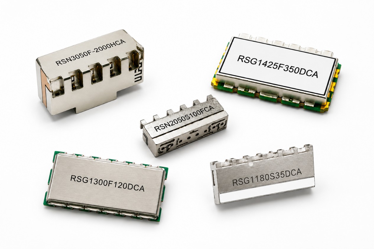
The Starlink Electromagnetic Landscape and the Challenge of Interference
To understand the necessity of RF filters, one must first examine the frequency architecture of LEO satellite systems. Starlink satellites primarily utilize the following frequency bands:
- Ku-band (12–18 GHz): Primarily used for user downlinks (satellite to user terminal) and uplinks (user terminal to satellite).
- Ka-band (26.5–40 GHz): Typically reserved for gateway links connecting the satellites to ground-based internet backbones.
- E-band (71–86 GHz): Increasingly utilized for high-capacity gateway backhaul links in newer satellite generations.
[Space-Based Satellites]
│ ▲ (Ku/Ka-band links)
▼ │
[Ground Gateways & User Terminals (Dishy)] ◄─── (Interference from 5G, Radar, & Microwave Links)
At these high frequencies, signals suffer from atmospheric attenuation, rain fade, and path loss. Crucially, the airwaves are shared. The Ku and Ka bands run adjacent to frequencies allocated for terrestrial 5G networks, military radar systems, and point-to-point microwave links. Without precise frequency management, out-of-band signals from these terrestrial sources can easily spill over into the satellite receiver's operating band.
When a receiver is flooded with strong, unwanted out-of-band signals, its Low Noise Amplifier (LNA) can become saturated. This phenomenon, known as receiver desensitization or "blocking," prevents the receiver from processing the actual, much weaker satellite signal. Consequently, users experience dropped connections, high packet loss, and reduced data throughput.
How RF Filters Improve Starlink Performance
RF filters are passive devices designed to allow signals within a specific frequency range (the passband) to pass through while heavily attenuating signals outside that range (the stopband). In Starlink systems, they are deployed at various stages of the RF front-end to achieve several critical performance improvements:
1. Mitigating Out-of-Band Interference and LNA Protection
In any satellite receiver—whether it is a ground gateway or a home terminal (often referred to as "Dishy")—the very first active component after the antenna is the Low Noise Amplifier (LNA). The LNA is highly sensitive and designed to amplify incredibly faint signals arriving from space.
By placing a high-rejection bandpass filter directly before the LNA, engineers can ensure that only the desired satellite carrier signals reach the amplifier. The filter blocks strong, interfering signals from nearby 5G base stations or radar installations. This protective measure prevents the LNA from entering compression, thereby maintaining its linearity and preserving the overall dynamic range of the receiver.
2. Minimizing Insertion Loss to Optimize Link Budget
In satellite communications, the "link budget" determines the reliability and speed of the connection. A critical factor in this budget is insertion loss—the amount of signal power lost when a signal passes through a component like a filter or a cable.
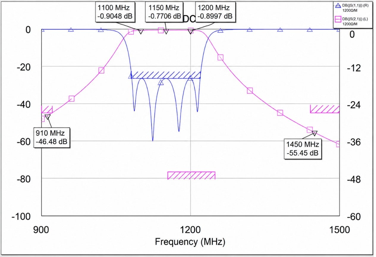
High-performance RF filters are engineered to have extremely low insertion loss within the passband (often less than 0.5 dB). Every tenth of a decibel saved in insertion loss directly improves the receiver’s Signal-to-Noise Ratio (SNR). For the end-user, this translates to faster upload and download speeds, more stable connections during poor weather (such as heavy rain or snow), and overall better network availability.
3. Enhancing Transmit-to-Receive (TX/RX) Isolation
Starlink terminals and satellites must transmit and receive data simultaneously—a capability known as full-duplex communication. Because the transmitter operates at a much higher power level than the receiver, the transmitted signal can easily leak into the local receiver circuit.
To prevent the transmitter from deafening its own receiver, diplexers and duplexers (which are specialized assemblies of bandpass filters) are utilized. These devices provide high isolation (often exceeding 50 dB to 60 dB) between the transmit (TX) and receive (RX) paths. This guarantees that the receiver can detect weak incoming signals from space even while the transmitter is broadcasting at full power.
┌───────────────┐
┌───────►│ TX Bandpass │◄────── Transmit Signal (High Power)
│ └───────────────┘
[Antenna]
│ ┌───────────────┐
└───────►│ RX Bandpass │──────► Receive LNA (Protected, Low Noise)
└───────────────┘
4. Ensuring Frequency Selectivity in Phase Array Antennas
Modern Starlink user terminals utilize electronically steered phased array antennas to track satellites moving rapidly across the sky. These phased arrays contain dozens or hundreds of tiny antenna elements, each requiring precise phase and amplitude control.
Integrating miniature, high-selectivity RF filters within the beamforming network ensures that the array only steers beams toward the intended satellite frequencies, suppressing sidelobe emissions and preventing off-axis interference from degrading the array’s performance.
Selecting the Right RF Filters: Cavity vs. LC vs. Ceramic
Different parts of the Starlink network require different types of filter technologies depending on size, cost, power handling, and performance requirements:
- Cavity Filters: These are highly favored in ground gateways and satellite payloads due to their exceptionally high Quality Factor (Q-factor), very low insertion loss, and high power-handling capabilities. They are constructed using resonant metallic cavities and are ideal for separating closely spaced frequency bands.
- Ceramic Filters: Offering a balance between performance and size, ceramic coaxial resonators are widely used in transceiver modules. They provide excellent temperature stability, which is vital for hardware exposed to outdoor environments.
- LC Filters (Lumped Element): Composed of discrete inductors and capacitors, LC filters are small and cost-effective, making them suitable for lower-frequency stages of the receiver circuitry where extreme selectivity is not the primary requirement.
RSwave’s Contribution to High-Performance RF Systems
For satellite communication equipment manufacturers and network integrators aiming to match or exceed the performance benchmarks of networks like Starlink, sourcing high-reliability RF components is essential. Jiaxing Ruishang Electronic Technology Co., Ltd. (RSwave), accessible at www.rswave.com, specializes in the design and production of high-performance RF and microwave components that are critical for these applications.
High-Performance RF Filters
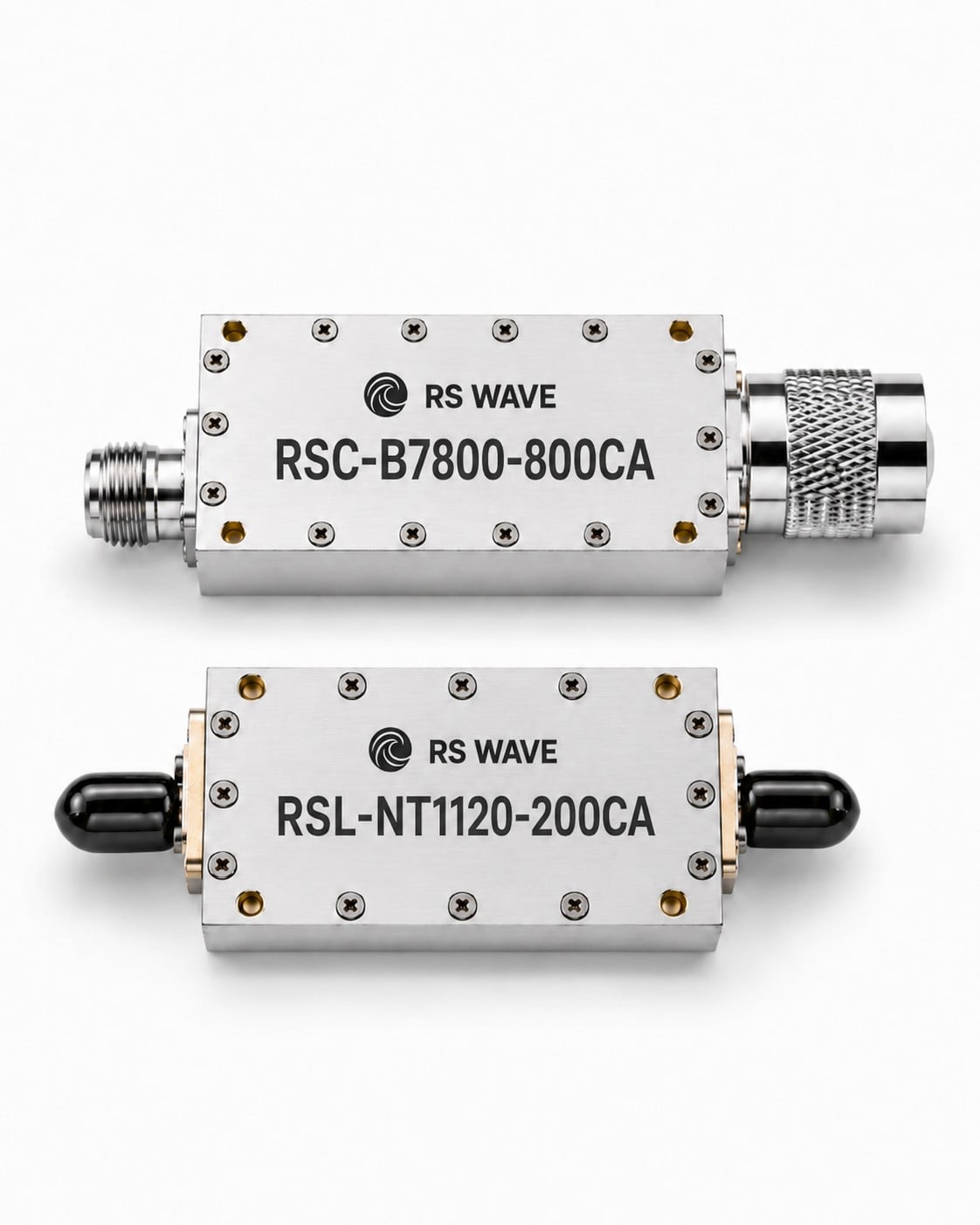
RSwave offers an extensive portfolio of RF filters, including custom-designed cavity bandpass filters, low-pass filters, and high-pass filters. These products are engineered to deliver the steep roll-off, high out-of-band rejection, and low insertion loss required to protect sensitive receiver architectures in satellite communication ground stations.
Coaxial Connectors and Adapters
A filter is only as good as the connections linking it to the rest of the RF chain. Impedance mismatches at the interface between the filter and the transmission line can cause signal reflections, increasing the Voltage Standing Wave Ratio (VSWR) and degrading system performance.
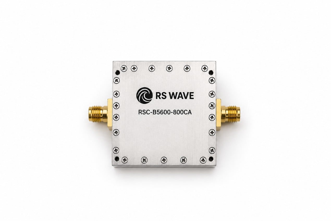
RSwave provides high-precision RF connectors (including SMA, N-type, TNC, and high-frequency millimeter-wave connectors like 2.92mm and 2.4mm) that ensure seamless, low-loss signal transitions up to 40 GHz and beyond.
Low-Loss RF Cable Assemblies
To connect antennas, filters, and LNAs inside gateway shelters or user terminals, low-loss and phase-stable coaxial cable assemblies are required. RSwave’s flexible and semi-rigid cable assemblies are designed to maintain signal integrity under fluctuating temperature conditions, preventing phase drift and signal attenuation.
Conclusion
As LEO satellite constellations like Starlink continue to expand, the demand for clean, interference-free spectrum will only increase. RF filters serve as the primary line of defense, ensuring that sensitive satellite receivers are protected from the growing sea of terrestrial radio signals. By minimizing insertion loss, maximizing out-of-band rejection, and ensuring high TX/RX isolation, these components directly enable the high-speed, low-latency performance that users expect from modern satellite internet.
For engineers and system integrators building the next generation of satellite ground stations, user terminals, or microwave links, partner companies like Jiaxing Ruishang Electronic Technology Co., Ltd. (RSwave) provide the specialized RF filters, connectors, and cable assemblies required to succeed. To explore their full catalog of high-frequency components and custom design capabilities, visit www.rswave.com.