
 EN
EN
In the rapidly expanding ecosystem of wireless communications, the electromagnetic spectrum has become increasingly crowded. With the simultaneous deployment of 5G networks, IoT devices, satellite communications, radar systems, and broadcasting services, RF co-existence has become one of the most critical challenges for RF engineers.
One of the most disruptive phenomena in this environment is receiver desensitization (or receiver blocking). This occurs when a strong, unwanted signal at a specific frequency penetrates a receiver system, saturating the Low Noise Amplifier (LNA) or mixer, and rendering the receiver incapable of detecting weaker, desired signals.
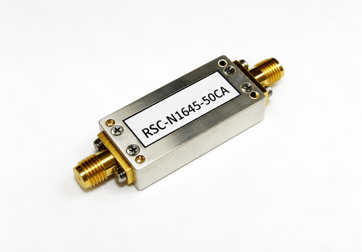
To combat this, RF engineers rely on high-performance filtering solutions. Among these, the notch filter (also known as a bandstop or band-rejection filter) serves as a surgical tool. This article explores how notch filters eliminate strong interference signals of specific frequencies, delves into the underlying engineering principles, and highlights how advanced cavity notch designs from Jiaxing Ruishang Electronics Co., Ltd. (RSwave) solve critical interference challenges in modern RF systems.
Understanding the Notch Filter: A Surgical Spectral Tool
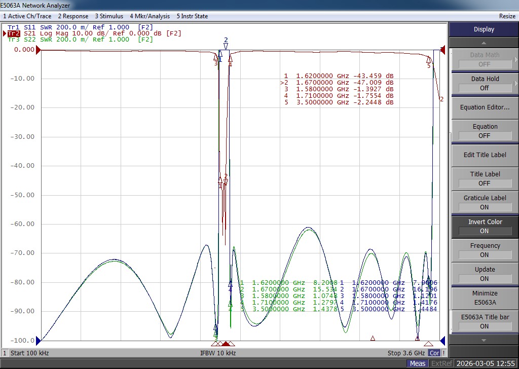
Unlike a bandpass filter that allows a specific band of frequencies to pass while attenuating everything else, or lowpass/highpass filters that divide the spectrum at a single cutoff frequency, a notch filter does the opposite. It passes almost all frequencies with minimal loss, except for a highly localized, narrow band of frequencies which it attenuates to extremely low levels.
Transmission (dB)
0 |-----------------\ /----------------- (Passband)
| \ /
| \ /
| \ /
-50 |---------------------\--o--/--------------------- (Stopband / Notch)
| f0
+------------------------------------------------- Frequency (Hz)
The primary parameters defining a notch filter include:
1.Center Frequency (f0f_0f0): The exact frequency where the attenuation (rejection) is maximized.
2.Rejection Depth (dB): The amount of signal suppression at f0f_0f0. For high-interference environments, a rejection depth of 40 dB40\text{ dB}40 dB to 80 dB80\text{ dB}80 dB or more is often required.
3.Passband Insertion Loss (dB): The loss experienced by the desired signals outside the notch. Ideally, this should be as close to 0 dB0\text{ dB}0 dB as possible (typically <1.0 dB< 1.0\text{ dB}<1.0 dB in high-quality cavity filters) to prevent signal degradation.
4.Q-Factor (Quality Factor): The ratio of the center frequency to the 3dB bandwidth (Q=f0/ΔfQ = f_0 / \Delta fQ=f0/Δf). A higher Q-factor indicates a narrower, sharper notch, allowing the filter to eliminate interference very close to the desired communication channel without affecting it.
How Notch Filters Eliminate Interference: The Mechanics of Rejection
To understand how a notch filter eliminates strong interference, we must look at how it interacts with the RF signal chain.
When a high-power interfering transmitter is located near a sensitive receiver, the out-of-band emissions or the fundamental frequency of the transmitter can overwhelm the receiver. Even if the interfering frequency is outside the receiver's operating band, if the signal is strong enough, it will drive the receiver’s frontend LNA into its non-linear region (compression). This leads to intermodulation distortion (IMD) and a dramatic rise in the receiver's noise floor.
[Antenna] --- [ Notch Filter (RSwave) ] --- [ LNA / Receiver Frontend ]
|
(Attenuates strong
interferer at f0;
passes desired band)
By placing an RF notch filter directly between the antenna and the receiver frontend, the incoming spectrum is modified:
- Reflecting the Interfering Energy: The notch filter acts as an impedance mismatch (high VSWR) at the unwanted frequency (f0f_0f0). Instead of entering the receiver, the energy of the interfering signal is reflected back or dissipated within the filter structure.
- Preserving Desired Signals: At the desired frequencies, the filter presents a matched impedance (usually 50 Ω50\ \Omega50 Ω), allowing the signals to pass into the LNA with negligible attenuation.
The Role of Cavity Notch Filters in High-Performance Systems
For demanding industrial, telecommunications, and defense applications, standard lumped-element (LC) notch filters often fall short. LC filters suffer from lower Q-factors, higher insertion losses, and limited power handling capabilities.
This is where Cavity Notch Filters become essential. Cavity filters utilize resonant metallic chambers to achieve exceptionally high Q-factors.
Why Cavity Designs Excel:
- Ultra-High Q-Factor: Cavity resonators store electromagnetic energy with minimal losses, resulting in extremely steep transition skirts. This allows engineers to place a deep notch immediately adjacent to a guard band.
- Low Insertion Loss: With silver-plated internal surfaces and high-conductivity metals, cavity notch filters keep passband insertion loss to a minimum, preserving system link budgets.
- High Power Handling: Cavity resonators can handle RF power levels ranging from tens of watts to kilowatts without experiencing thermal breakdown or tuning drift.
Real-World Applications: Where Notch Filters are Indispensable
1. Co-Location Site Mitigation (Cellular and Public Safety)
At co-located antenna sites, multiple transmitters and receivers share the same physical tower or rooftop. For example, a 450 MHz450\text{ MHz}450 MHz public safety transmitter can easily desensitize a nearby LTE receiver. A cavity notch filter tuned precisely to the public safety transmit frequency can be installed at the LTE receiver input to eliminate the interference, ensuring uninterrupted cellular coverage.
2. Broadcasting and TV White Space Protection
High-power FM transmitters (operating between 88 MHz88\text{ MHz}88 MHz and 108 MHz108\text{ MHz}108 MHz) and UHF TV stations generate massive RF energy. Nearby wireless microphone systems, amateur radio stations, or narrow-band IoT receivers must employ notch filters to suppress these strong broadcasting carriers.
3. Radar and Satellite Ground Station Protection
Satellite receivers operating in the C-band (3.7 GHz−4.2 GHz3.7\text{ GHz} - 4.2\text{ GHz}3.7 GHz−4.2 GHz) are increasingly subjected to interference from newly deployed 5G C-band transmitters. Implementing high-performance cavity notch filters allows ground stations to block out 5G carrier frequencies while receiving weak satellite downlinks.
Selecting and Designing the Right Notch Filter
Selecting the right notch filter requires careful consideration of several electrical and mechanical specifications:
Parameter |
Key Consideration |
Frequency Range |
The specific passbands and the exact stopband (notch frequency) required. |
Rejection Level |
How many decibels (dB) of attenuation are needed to bring the interferer below the receiver's threshold. |
Power Handling |
If placed on the transmit side, the filter must handle the full output power without passive intermodulation (PIM) distortion. |
Environmental Conditions |
Temperature stability is crucial. High-quality cavity filters utilize Invar tuning rods to prevent frequency drift over temperature changes (−40∘C-\text{40}^\circ\text{C}−40∘C to +85∘C+\text{85}^\circ\text{C}+85∘C). |
Form Factor & Connectors |
Connector types (e.g., SMA, N-type, 7/16 DIN) and physical dimensions must fit within the system chassis. |
At Jiaxing Ruishang Electronics Co., Ltd. (RSwave), we specialize in the design, simulation, and manufacturing of custom RF cavity filters, duplexers, and notch filters. Utilizing advanced 3D electromagnetic simulation software (HFSS) and precision machining, RSwave delivers filters tailored to exact frequency profiles, ensuring optimal suppression of interference with minimal impact on adjacent signals.
Conclusion
As the wireless landscape continues to grow, spectral congestion is an unavoidable reality. Strong interference signals of specific frequencies do not have to compromise system performance. By deploying precisely engineered notch filters, RF professionals can surgically isolate and eliminate interfering signals, protecting sensitive receivers and maximizing spectral efficiency.
For high-reliability communication networks, choosing the right filter partner is critical. Jiaxing Ruishang Electronics Co., Ltd. (RSwave) provides a comprehensive portfolio of high-Q cavity notch filters, bandstop filters, and custom RF components engineered to meet the highest industry standards.
To explore our full range of RF filtering solutions, view product datasheets, or discuss custom design requirements with our engineering team, visit our official website at www.rswave.com.
Table of Contents
- Understanding the Notch Filter: A Surgical Spectral Tool
- How Notch Filters Eliminate Interference: The Mechanics of Rejection
- The Role of Cavity Notch Filters in High-Performance Systems
- Real-World Applications: Where Notch Filters are Indispensable
- Selecting and Designing the Right Notch Filter
- Conclusion