
The microwave resonator filter represents a critical component in modern RF and microwave communication systems, serving as the backbone for signal processing and frequency selection. These sophisticated devices operate by utilizing resonant cavities or structures that selectively allow certain frequencies to pass while blocking others, making them indispensable in applications ranging from cellular base stations to satellite communications. Understanding the fundamental principles behind microwave resonator filter operation is essential for engineers working in telecommunications, radar systems, and wireless technology development. The intricate design and precise manufacturing requirements of these filters demand comprehensive knowledge of electromagnetic field theory, materials science, and advanced manufacturing techniques.
Fundamental Operating Principles
Electromagnetic Resonance Theory
The operational foundation of a microwave resonator filter lies in the phenomenon of electromagnetic resonance, where specific frequencies create standing wave patterns within carefully designed cavities or structures. When electromagnetic energy enters the resonator at its resonant frequency, the electric and magnetic fields establish a stable oscillating pattern that efficiently stores and transfers energy. This resonance occurs when the physical dimensions of the cavity correspond to integer multiples of half-wavelengths at the operating frequency, creating constructive interference that amplifies the desired signal while suppressing unwanted frequencies through destructive interference.
The quality factor, commonly referred to as Q-factor, plays a crucial role in determining the performance characteristics of the resonator filter. Higher Q-factors indicate lower energy losses and narrower bandwidth responses, resulting in more selective filtering capabilities. The relationship between the stored energy and the power dissipated per cycle directly influences the sharpness of the filter response and its ability to distinguish between closely spaced frequencies in complex signal environments.
Coupling Mechanisms and Energy Transfer
Energy coupling in microwave resonator filters occurs through various mechanisms including magnetic loops, electric probes, and aperture coupling, each offering distinct advantages depending on the specific application requirements. Magnetic coupling utilizes small loops positioned within the magnetic field regions of the resonator to transfer energy with minimal perturbation to the electric field distribution. Electric coupling employs probes or gaps that interact primarily with the electric field components, providing different impedance matching characteristics and frequency response shapes.
The degree of coupling directly affects the bandwidth and insertion loss characteristics of the filter, with critical coupling providing optimal power transfer while maintaining desired selectivity. Over-coupling results in increased bandwidth but higher insertion losses, while under-coupling produces narrower bandwidth responses with reduced power transfer efficiency. Engineers must carefully balance these trade-offs during the design phase to achieve optimal performance for specific system requirements.
Design Configurations and Structures
Cavity Resonator Architectures
Traditional cavity resonator filters employ metallic enclosures with precisely machined internal dimensions to create the desired resonant modes and frequency responses. These structures typically utilize rectangular, cylindrical, or custom-shaped cavities depending on the required electromagnetic field distributions and mechanical constraints. The internal surfaces often feature high-conductivity materials or specialized coatings to minimize ohmic losses and maximize the Q-factor performance critical for demanding applications.
Modern cavity designs incorporate tuning elements such as adjustable screws, dielectric inserts, or movable walls that allow post-manufacturing frequency adjustment and temperature compensation. These tuning mechanisms enable fine-tuning of the resonant frequencies to accommodate manufacturing tolerances and environmental variations while maintaining optimal filter performance throughout the operational temperature range.
Dielectric Resonator Implementations
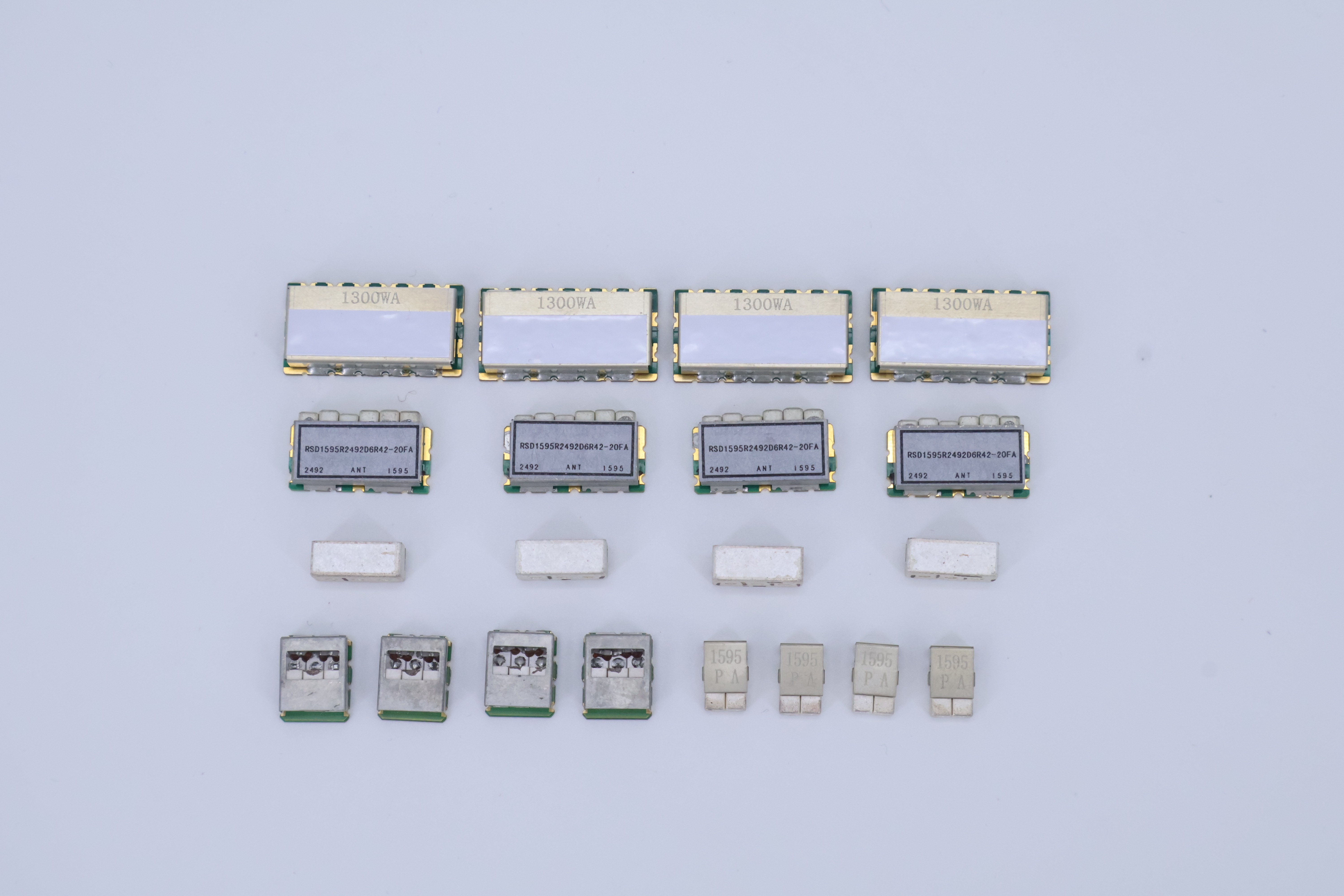
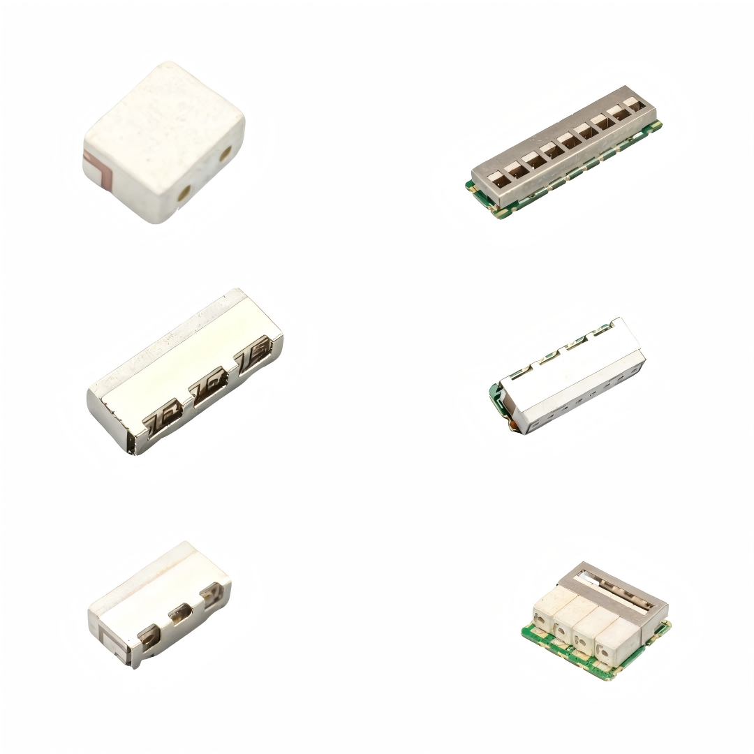
Dielectric resonator filters utilize high-permittivity ceramic materials to create compact, high-performance filtering solutions that offer significant size reductions compared to traditional cavity designs. The microwave resonator filter technology leverages advanced dielectric materials with temperature-stable properties and low loss tangents to achieve excellent electrical performance in miniaturized packages. These ceramic resonators can be configured in various geometries including cylindrical, rectangular, and custom shapes optimized for specific frequency bands and performance requirements.
The electromagnetic fields in dielectric resonators are primarily confined within the ceramic material, resulting in improved isolation between adjacent resonators and reduced spurious mode coupling. This field confinement also enables closer spacing of multiple resonators within multi-pole filter designs, further contributing to size reduction benefits while maintaining excellent electrical performance characteristics.
Performance Characteristics and Specifications
Frequency Response and Selectivity
The frequency response of microwave resonator filters exhibits characteristic passband and stopband regions that define the filter's selectivity and rejection capabilities. The passband region allows desired frequencies to pass with minimal attenuation, while the stopband regions provide high attenuation to unwanted signals and interference. The transition between these regions, known as the filter skirt, determines how quickly the attenuation increases outside the passband and directly impacts the filter's ability to separate closely spaced signals.
Insertion loss within the passband represents the unavoidable signal attenuation that occurs even at the desired frequencies due to conductor losses, dielectric losses, and coupling inefficiencies. Modern microwave resonator filter designs achieve insertion losses typically ranging from 0.5 to 3 dB depending on the filter complexity, frequency band, and Q-factor requirements. Return loss measurements indicate how well the filter impedance matches the system impedance, with higher return loss values indicating better impedance matching and reduced signal reflections.
Temperature Stability and Environmental Performance
Temperature variations significantly affect the performance of microwave resonator filters through thermal expansion of mechanical components and temperature-dependent changes in material properties. The temperature coefficient of frequency describes how the resonant frequency shifts with temperature changes, typically expressed in parts per million per degree Celsius. Advanced filter designs incorporate temperature compensation techniques such as bimetallic elements, composite materials with opposing temperature coefficients, or active temperature control systems to maintain stable performance across wide temperature ranges.
Environmental factors including humidity, vibration, and shock also influence filter performance and reliability. Hermetic sealing techniques protect sensitive internal components from moisture ingress that could degrade electrical performance or cause corrosion over time. Mechanical mounting systems must provide adequate vibration isolation while maintaining precise dimensional stability to preserve the critical resonator spacing and coupling relationships that determine filter performance.
Manufacturing Techniques and Quality Control
Precision Machining and Assembly Processes
Manufacturing microwave resonator filters requires extremely precise machining tolerances, typically measured in micrometers, to achieve the required frequency accuracy and performance specifications. Computer numerical control machining centers equipped with high-resolution measurement systems enable the production of complex cavity geometries with the dimensional accuracy necessary for reliable filter performance. Surface finish quality significantly impacts conductor losses, requiring specialized machining techniques and post-processing treatments to achieve the smooth surfaces essential for high Q-factor performance.
Assembly processes must maintain the tight tolerances established during machining while ensuring robust mechanical connections and proper electromagnetic continuity throughout the filter structure. Specialized fixtures and alignment systems guide the assembly process to prevent dimensional errors that could compromise electrical performance. Quality control measures include dimensional inspection, electrical testing, and environmental stress screening to verify that each filter meets the specified performance requirements before shipment to customers.
Advanced Materials and Surface Treatments
Modern microwave resonator filter manufacturing utilizes advanced materials and surface treatment technologies to optimize electrical and mechanical performance characteristics. High-conductivity materials such as silver, gold, or specialized alloys provide superior electrical properties while offering excellent corrosion resistance and long-term stability. Plating processes must achieve uniform thickness distribution and excellent adhesion to ensure consistent electrical performance and reliability throughout the product lifetime.
Surface treatment techniques including passivation, anodizing, and specialized coatings enhance durability and environmental resistance while maintaining the critical electrical properties required for optimal filter performance. These treatments also provide protection against oxidation, corrosion, and wear that could degrade performance over time in demanding operational environments.
Applications and System Integration
Telecommunications Infrastructure
Microwave resonator filters play essential roles in telecommunications infrastructure including cellular base stations, microwave backhaul systems, and satellite communication terminals. These applications demand high selectivity to separate closely spaced channels while maintaining low insertion loss to preserve signal strength and system efficiency. The filters must handle high power levels while providing excellent intermodulation performance to prevent interference between multiple simultaneous signals operating within the same system.
Base station applications require filters that can operate reliably in outdoor environments while meeting stringent electrical specifications for channel separation and spurious emission suppression. The mechanical robustness and temperature stability of microwave resonator filter designs make them ideal for these demanding applications where long-term reliability is critical for network performance and availability.
Radar and Defense Systems
Military and aerospace applications utilize microwave resonator filters in radar systems, electronic warfare equipment, and satellite communications where performance requirements often exceed those of commercial applications. These systems frequently operate across wide temperature ranges and must maintain precise frequency responses despite environmental stresses including vibration, shock, and electromagnetic interference. The high Q-factor and excellent selectivity characteristics of resonator filters enable effective signal processing in complex electromagnetic environments typical of defense applications.
Radar applications particularly benefit from the superior phase linearity and group delay characteristics achievable with properly designed microwave resonator filters. These properties preserve pulse shape integrity and timing accuracy essential for target detection and ranging measurements in both surveillance and tracking radar systems.
Future Developments and Emerging Technologies
Advanced Manufacturing Techniques
Emerging manufacturing technologies including additive manufacturing and advanced ceramic processing techniques promise to revolutionize microwave resonator filter production by enabling complex geometries and integrated functionality previously impossible with conventional machining methods. Three-dimensional printing of metallic and ceramic components allows the creation of intricate internal structures that optimize electromagnetic field distributions while reducing size and weight compared to traditional designs.
Automated assembly systems incorporating machine vision and robotic handling capabilities improve manufacturing consistency while reducing production costs and lead times. These advanced manufacturing approaches enable the economical production of customized filter designs tailored to specific application requirements without the traditional tooling investments associated with high-volume production.
Integration with Active Components
Future microwave resonator filter developments focus on integration with active components such as amplifiers, oscillators, and digital control systems to create intelligent filtering solutions with adaptive characteristics. These integrated systems can automatically adjust their frequency response, bandwidth, and other characteristics based on real-time signal analysis and system requirements. Software-defined filtering capabilities enable single hardware platforms to support multiple frequency bands and modulation schemes through programmable control interfaces.
The integration of microelectromechanical systems technology enables the development of tunable microwave resonator filters with electronically controlled frequency responses and bandwidth characteristics. These adaptive filtering solutions provide unprecedented flexibility for software-defined radio applications and cognitive radio systems that must dynamically adapt to changing spectrum conditions and communication requirements.
FAQ
What factors determine the Q-factor of a microwave resonator filter
The Q-factor of a microwave resonator filter depends primarily on conductor losses in metallic surfaces, dielectric losses in insulating materials, radiation losses from discontinuities or apertures, and coupling losses at input and output interfaces. Higher Q-factors are achieved through the use of high-conductivity materials, low-loss dielectrics, careful design to minimize radiation, and optimized coupling mechanisms. Surface finish quality significantly impacts conductor losses, while material selection affects both dielectric and conductor loss contributions to the overall Q-factor performance.
How does temperature affect microwave resonator filter performance
Temperature variations cause frequency shifts in microwave resonator filters through thermal expansion of mechanical components and temperature-dependent changes in material properties including dielectric constant and conductivity. Most filters exhibit positive temperature coefficients where frequency increases with temperature, although the magnitude depends on materials and construction techniques. Compensation methods include using materials with opposing temperature coefficients, bimetallic tuning elements, or active temperature control systems to maintain stable performance across operational temperature ranges.
What are the main advantages of dielectric resonator filters compared to cavity filters
Dielectric resonator filters offer significant size and weight reductions compared to conventional cavity filters while maintaining excellent electrical performance characteristics. The high permittivity of ceramic materials concentrates electromagnetic fields within smaller volumes, enabling compact designs suitable for portable and space-constrained applications. Additionally, dielectric resonators provide improved temperature stability, reduced spurious mode coupling, and better mechanical ruggedness compared to traditional cavity designs, making them attractive for demanding commercial and military applications.
How do coupling mechanisms affect filter bandwidth and insertion loss
The coupling strength between resonators and external circuits directly controls the filter bandwidth and insertion loss characteristics through the relationship between stored energy and power transfer rates. Stronger coupling increases bandwidth but may also increase insertion loss due to impedance mismatch effects, while weaker coupling produces narrower bandwidth with potentially lower insertion loss but reduced power handling capability. Critical coupling provides optimal power transfer with minimal reflection, while over-coupling and under-coupling represent design trade-offs between bandwidth, insertion loss, and power handling requirements for specific applications.