
In the realm of electronic filtering technology, engineers frequently encounter the challenge of selecting appropriate frequency-selective components for their circuit designs. Two commonly utilized filtering solutions that often generate confusion are the LC band-stop filter and the traditional notch filter. While both serve similar fundamental purposes in attenuating specific frequency ranges, their underlying design principles, performance characteristics, and application scenarios differ significantly. Understanding these distinctions becomes crucial for engineers working in telecommunications, signal processing, and RF applications where precise frequency control determines system performance and reliability.
The fundamental concept of frequency rejection involves creating specific impedance characteristics that prevent signal transmission within targeted frequency bands. Both LC band-stop filter configurations and conventional notch filter designs achieve this objective through different methodologies, each offering unique advantages depending on the specific application requirements. The selection process requires careful consideration of factors including bandwidth requirements, insertion loss specifications, temperature stability, and manufacturing constraints that influence overall system performance.
Fundamental Design Architecture
LC Band-Stop Filter Construction
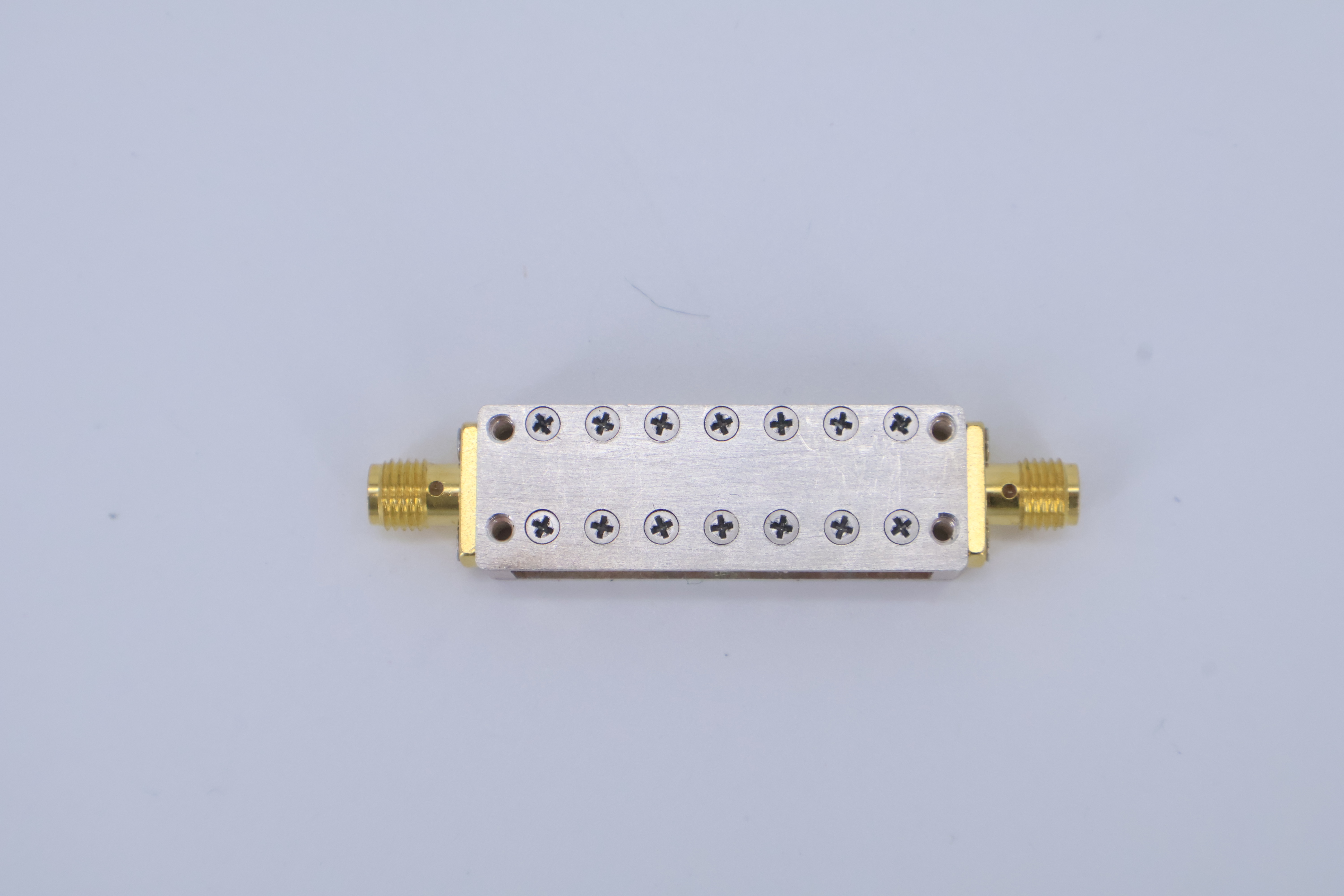
The lc band-stop filter employs inductors and capacitors arranged in specific topologies to create frequency-selective rejection characteristics. The most common configuration utilizes parallel LC resonant circuits connected in series with the signal path, creating high impedance conditions at the resonant frequency. This arrangement effectively blocks signal transmission within the designed stopband while maintaining minimal insertion loss in the passband regions.
The design process for an lc band-stop filter involves calculating precise component values based on the desired center frequency, bandwidth, and impedance matching requirements. Engineers must consider the quality factor of individual components, as this parameter directly influences the sharpness of the rejection characteristic and the overall filter performance. Higher quality factor components typically result in sharper rejection slopes but may increase manufacturing costs and temperature sensitivity.
Multiple-section lc band-stop filter designs can achieve enhanced rejection characteristics by cascading several resonant circuits with carefully calculated frequency spacing. This approach allows engineers to create wider stopbands or achieve greater attenuation depths while maintaining acceptable passband performance. The interaction between sections requires sophisticated design techniques to prevent unwanted resonances and ensure stable operation across varying environmental conditions.
Traditional Notch Filter Architecture
Traditional notch filters encompass various implementation methods including active filters using operational amplifiers, digital signal processing algorithms, and specialized analog circuits. Active notch filters typically employ operational amplifiers with feedback networks containing resistors and capacitors to create the desired frequency response. These implementations offer advantages in terms of tunability and integration with other circuit functions but may introduce noise and require power supplies.
Digital notch filter implementations utilize mathematical algorithms to process sampled signals and remove specific frequency components through computational methods. These approaches provide exceptional flexibility in terms of frequency adjustment and can achieve very precise rejection characteristics. However, digital implementations introduce quantization noise and require analog-to-digital conversion processes that may limit their applicability in certain high-frequency or analog-only systems.
Specialized analog notch circuits may employ transmission line elements, crystal resonators, or other frequency-selective components to achieve narrow-band rejection characteristics. These implementations often provide superior performance in specific applications but may lack the broad applicability and design flexibility offered by lc band-stop filter configurations.
Performance Characteristics and Specifications
Frequency Response Properties
The frequency response characteristics of an lc band-stop filter exhibit distinct features that differentiate them from other notch filter implementations. The rejection bandwidth depends primarily on the loaded quality factor of the resonant circuit, with higher Q values producing narrower stopbands and sharper transition regions. The insertion loss within the passband typically remains low, often less than 1 dB for well-designed circuits, making lc band-stop filter solutions attractive for applications requiring minimal signal degradation.
Temperature stability represents a critical performance parameter for lc band-stop filter designs, as both inductors and capacitors exhibit temperature-dependent characteristics that can shift the center frequency and alter the rejection depth. Advanced designs incorporate temperature-compensating techniques using components with opposite temperature coefficients or specialized materials that maintain stable performance across wide temperature ranges.
The power handling capability of an lc band-stop filter depends on the current-carrying capacity of the inductor and the voltage rating of the capacitor. Proper thermal management becomes essential in high-power applications to prevent component degradation and maintain consistent performance. The nonlinear behavior of magnetic materials in inductors can introduce harmonic distortion at high signal levels, requiring careful component selection and circuit optimization.
Bandwidth and Selectivity Considerations
Bandwidth control in lc band-stop filter designs involves adjusting the loaded Q factor through proper impedance matching and component selection. Narrow bandwidth applications require high-Q components and careful attention to parasitic elements that can degrade selectivity. The achievable bandwidth typically ranges from less than 1% to over 20% of the center frequency, depending on the specific design requirements and component limitations.
Selectivity refers to the sharpness of the transition between passband and stopband regions, quantified by the slope of the rejection characteristic measured in decibels per octave. An lc band-stop filter can achieve selectivity values comparable to other passive filter technologies while maintaining the advantages of simple construction and reliable operation. Multiple-section designs enhance selectivity at the expense of increased complexity and component count.
The out-of-band rejection characteristics of an lc band-stop filter depend on the order of the filter design and the specific circuit topology employed. Higher-order filters provide greater rejection but may exhibit unwanted resonances at harmonic frequencies that require additional design considerations. Proper grounding techniques and shielding become increasingly important as filter complexity increases to prevent electromagnetic interference and maintain predicted performance.
Application Scenarios and Use Cases
Telecommunications and RF Systems
In telecommunications applications, lc band-stop filter implementations serve crucial roles in eliminating interference from specific frequency sources while preserving desired signal content. Base station equipment frequently employs these filters to reject spurious emissions and prevent intermodulation distortion that can degrade system performance. The robust construction and predictable characteristics of lc band-stop filter designs make them suitable for outdoor installations where environmental reliability becomes paramount.
Satellite communication systems utilize lc band-stop filter technology to suppress unwanted frequency components that could interfere with sensitive receiver circuits. The low insertion loss characteristics prove particularly valuable in these applications where signal levels are typically very low and any additional loss directly impacts system sensitivity. Space-qualified components ensure reliable operation in the harsh environmental conditions encountered in satellite applications.
Mobile communication devices integrate lc band-stop filter elements to meet regulatory emission requirements and prevent interference with other electronic systems. The compact size and integration capabilities of modern lc band-stop filter designs enable implementation in space-constrained applications while maintaining the necessary performance specifications. Advanced materials and manufacturing techniques continue to reduce the size and cost of these filtering solutions.
Industrial and Measurement Applications
Industrial control systems often require lc band-stop filter solutions to eliminate power line interference and other environmental noise sources that can affect sensitive measurement circuits. The passive nature of these filters ensures reliable operation without requiring additional power supplies or complex control circuits. This simplicity translates to reduced maintenance requirements and improved system reliability in harsh industrial environments.
Test and measurement equipment incorporates lc band-stop filter technology to improve measurement accuracy by eliminating known interference sources. The predictable performance characteristics enable precise calibration procedures and ensure consistent results across multiple measurement sessions. Low phase distortion properties make these filters particularly suitable for applications requiring preservation of signal timing relationships.
Medical equipment applications benefit from the electromagnetic compatibility improvements provided by properly designed lc band-stop filter implementations. The ability to reject specific frequency bands that correspond to common interference sources helps ensure reliable operation of critical medical devices. Regulatory compliance requirements often mandate the use of filtering solutions to prevent equipment from causing or being susceptible to electromagnetic interference.
Design Considerations and Trade-offs
Component Selection and Optimization
Selecting appropriate components for an lc band-stop filter requires careful analysis of the trade-offs between performance, cost, and manufacturing considerations. High-Q inductors typically provide superior filter performance but may be more expensive and exhibit greater temperature sensitivity. The choice of inductor core material affects both the Q factor and the power handling capability, with air-core designs offering excellent linearity but larger physical size compared to ferrite or powdered iron alternatives.
Capacitor selection for lc band-stop filter applications involves evaluating dielectric materials, temperature coefficients, and voltage ratings to ensure optimal performance across the intended operating conditions. Ceramic capacitors offer excellent stability and small size but may exhibit voltage-dependent capacitance that can affect filter performance at high signal levels. Film capacitors provide superior linearity but typically require more space and may be more expensive for high-capacitance values.
Parasitic elements including component tolerances, lead inductance, and stray capacitance can significantly impact the performance of an lc band-stop filter, particularly at higher frequencies. Advanced design techniques including electromagnetic simulation and careful layout optimization help minimize these effects and ensure that the actual performance matches the theoretical predictions. Component aging characteristics must also be considered to maintain long-term performance stability.
Manufacturing and Cost Factors
The manufacturing processes for lc band-stop filter assemblies influence both the achievable performance and the production costs. Automated assembly techniques can reduce labor costs but may require standardized component packages and specific design constraints. Hand-assembly methods offer greater flexibility in component selection and optimization but typically result in higher production costs and potential variations between individual units.
Quality control procedures for lc band-stop filter production must verify both the individual component values and the overall filter performance to ensure compliance with specifications. Automated test equipment can efficiently measure frequency response characteristics and identify units that fall outside acceptable tolerance ranges. Statistical process control techniques help optimize manufacturing yields and identify potential process improvements.
Cost optimization strategies for lc band-stop filter designs often involve standardizing component values to enable volume purchasing advantages and reduce inventory complexity. Design techniques that utilize commonly available component values while achieving the required performance specifications can significantly reduce overall system costs. The total cost of ownership includes not only the initial component costs but also assembly, testing, and field maintenance expenses.
Comparison with Alternative Technologies
Active Filter Implementations
Active filter designs using operational amplifiers can achieve similar frequency response characteristics to lc band-stop filter implementations but with different trade-offs in terms of power consumption, noise performance, and frequency range limitations. Active filters offer advantages in terms of tunability and the ability to achieve high Q values without requiring expensive high-quality passive components. However, they introduce noise and distortion that may be unacceptable in sensitive applications.
The frequency limitations of operational amplifiers restrict the upper frequency range of active notch filters, while lc band-stop filter designs can operate effectively well into the gigahertz range with appropriate component selection and circuit layout techniques. Power supply requirements for active filters add complexity and potential reliability concerns compared to the passive nature of lc band-stop filter solutions.
Programmable active filters offer exceptional flexibility in adjusting frequency response characteristics through digital control interfaces, enabling adaptive filtering capabilities that are not possible with fixed lc band-stop filter designs. This flexibility comes at the cost of increased complexity, power consumption, and potential susceptibility to digital noise and interference.
Digital Signal Processing Solutions
Digital signal processing implementations of notch filtering provide unmatched flexibility and precision in defining frequency response characteristics. These solutions can implement complex filter shapes and adaptive algorithms that automatically adjust to changing interference conditions. However, they require analog-to-digital conversion processes that introduce quantization noise and sampling rate limitations that may not be suitable for all applications.
The computational requirements of digital notch filters can be substantial, particularly for real-time applications with strict latency requirements. Modern digital signal processors and field-programmable gate arrays provide sufficient processing power for most applications, but the associated cost and power consumption may exceed that of equivalent lc band-stop filter solutions.
Hybrid approaches combining lc band-stop filter elements with digital signal processing can leverage the advantages of both technologies while mitigating their respective limitations. Pre-filtering with passive components reduces the dynamic range requirements for digital converters, while digital processing provides fine adjustment capabilities and adaptive functionality.
FAQ
What are the main advantages of using an lc band-stop filter over other notch filter types
The primary advantages of lc band-stop filter designs include their passive operation requiring no external power supply, excellent reliability due to the absence of active components, and superior performance at high frequencies where active solutions may be limited. These filters also offer predictable performance characteristics, low insertion loss in passband regions, and the ability to handle high power levels without distortion. Additionally, lc band-stop filter implementations typically exhibit excellent electromagnetic compatibility and can operate in harsh environmental conditions where active circuits might fail.
How does temperature affect the performance of an lc band-stop filter
Temperature variations affect both the inductance and capacitance values in an lc band-stop filter, causing shifts in the center frequency and changes in the bandwidth and rejection depth. Typical temperature coefficients for standard components can result in frequency shifts of several percent over military temperature ranges. However, temperature-compensated designs using components with opposing temperature coefficients or specialized low-temperature-coefficient materials can maintain frequency stability within a few parts per million per degree Celsius, making them suitable for precision applications requiring stable performance across wide temperature ranges.
What frequency ranges are most suitable for lc band-stop filter applications
LC band-stop filter designs are most effective in frequency ranges from approximately 1 MHz to several GHz, where practical inductor and capacitor values can be realized with reasonable component sizes and costs. Below 1 MHz, the required inductance values become very large and may exhibit poor Q factors, while above several GHz, parasitic elements and distributed effects begin to dominate component behavior. The optimal frequency range for most applications falls between 10 MHz and 1 GHz, where high-performance components are readily available and circuit layout techniques can effectively control parasitic effects.
Can multiple lc band-stop filter sections be combined to create wider stopbands
Yes, multiple lc band-stop filter sections can be cascaded to create wider stopbands or achieve greater attenuation depths by carefully designing each section to operate at slightly different frequencies. This approach allows engineers to create complex rejection characteristics that would be difficult to achieve with a single resonant circuit. However, the interaction between sections must be carefully analyzed to prevent unwanted resonances and ensure that the overall filter performance meets the design specifications. Proper impedance matching between sections is essential to maintain low insertion loss in the passband regions and achieve the predicted rejection characteristics.
Table of Contents
- Fundamental Design Architecture
- Performance Characteristics and Specifications
- Application Scenarios and Use Cases
- Design Considerations and Trade-offs
- Comparison with Alternative Technologies
-
FAQ
- What are the main advantages of using an lc band-stop filter over other notch filter types
- How does temperature affect the performance of an lc band-stop filter
- What frequency ranges are most suitable for lc band-stop filter applications
- Can multiple lc band-stop filter sections be combined to create wider stopbands