
 EN
EN
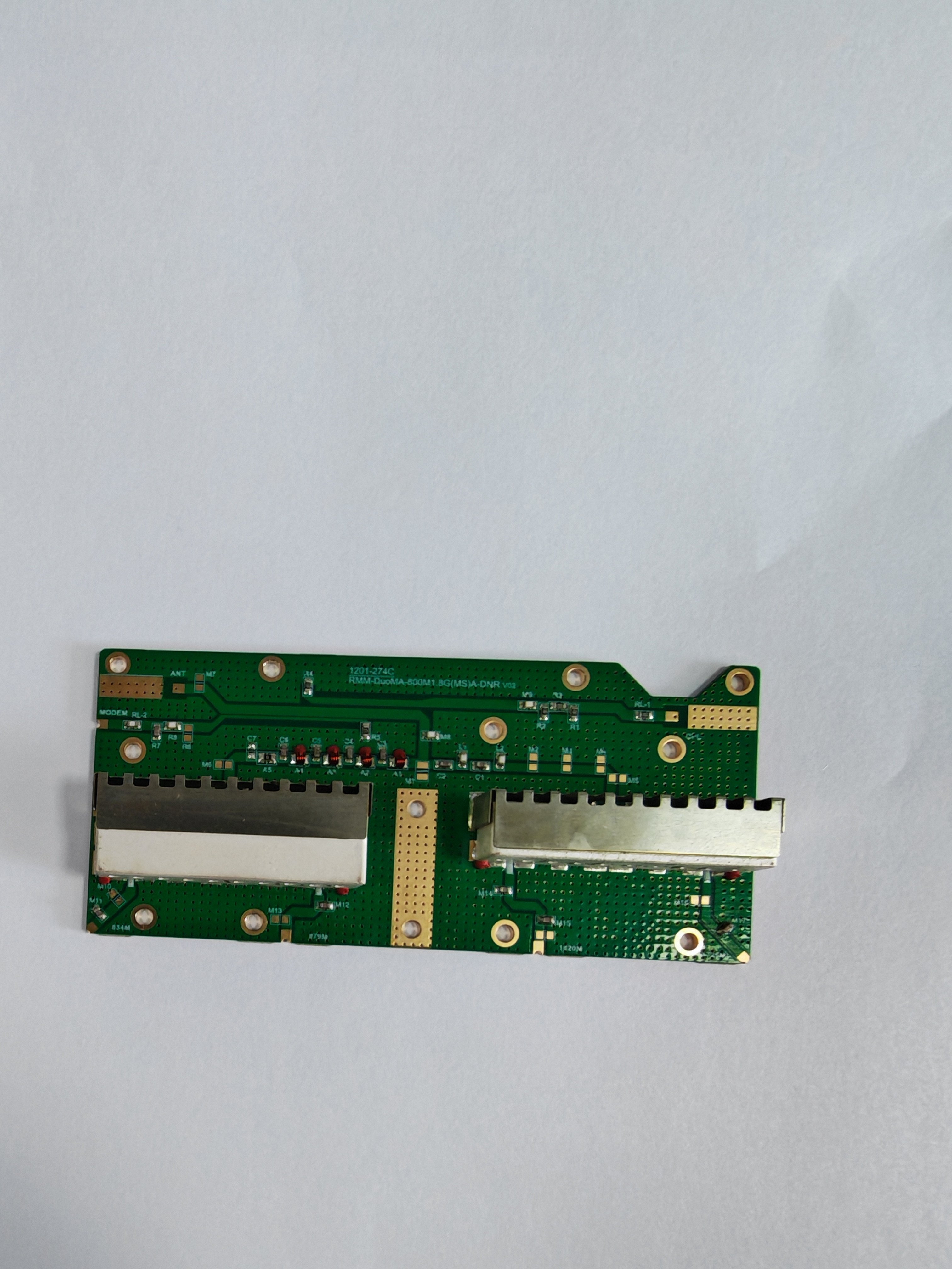
A microwave resonator duplexer is a sophisticated RF component that enables wireless communication systems to transmit and receive signals simultaneously on the same antenna without interference. This critical technology allows telecommunications infrastructure, radar systems, and satellite communications to operate efficiently by separating outbound and inbound signals through precise frequency filtering. Understanding how a microwave resonator duplexer works is essential for engineers, procurement specialists, and systems designers who need to optimize communication performance and system reliability.
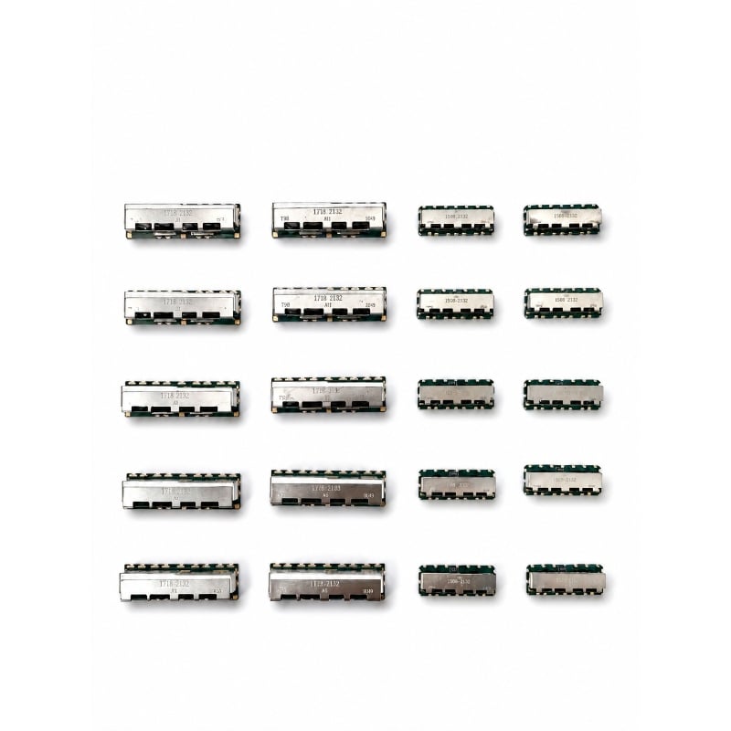
The fundamental function of a microwave resonator duplexer is frequency isolation. Without this technology, transmitted and received signals would collide on a shared antenna, creating destructive interference that would compromise communication integrity. A microwave resonator duplexer solves this problem by using resonant cavities and filtering techniques to allow transmit frequencies to pass in one direction while simultaneously routing receive frequencies in another direction, all while maintaining signal quality and minimizing loss.
Core Operating Principles of Microwave Resonator Duplexer Design
Resonant Cavity Architecture
The microwave resonator duplexer operates using resonant cavities that vibrate at specific frequencies determined by their physical dimensions. These cavities function as electromagnetic containers that concentrate and amplify signals at target frequencies while suppressing unwanted signals. A microwave resonator duplexer contains multiple cavity sections, typically configured in a transmit path and a receive path, each tuned to distinct frequency bands. The physical design of each cavity within the microwave resonator duplexer must be precise, as even minor dimensional variations can shift the resonant frequency and degrade performance. Engineers calculate cavity dimensions using electromagnetic simulation software to ensure the microwave resonator duplexer achieves the required frequency response across its operating range.
Signal Routing and Isolation Mechanisms
A microwave resonator duplexer routes signals through directional coupling and isolation ports that prevent cross-talk between transmit and receive channels. The transmit signal enters the microwave resonator duplexer through one port, passes through the transmit cavity section, and exits through the antenna port with minimal loss. Simultaneously, the received signal enters through the same antenna port but follows a separate internal path through the receive cavity section, exiting through a distinct receive port. This physical separation within the microwave resonator duplexer is achieved using internal waveguides and coupling structures that create frequency-selective pathways. The isolation between transmit and receive paths in a microwave resonator duplexer typically exceeds 50 decibels, meaning the unwanted signal leakage remains negligible relative to the desired signals.
Frequency Filtering and Resonance Tuning Mechanisms
Selective Frequency Response
The microwave resonator duplexer employs high-Q resonators that exhibit sharply tuned frequency responses. Quality factor, or Q, measures how selectively a resonator responds to frequencies near its resonant point. A microwave resonator duplexer with high Q values maintains strong response at target frequencies while rapidly attenuating off-frequency signals. This selectivity is crucial because transmit and receive bands in real communication systems are often separated by only tens to hundreds of megahertz, requiring the microwave resonator duplexer to provide excellent frequency discrimination. The microwave resonator duplexer achieves this through precise cavity geometry, high-conductivity materials, and sometimes tunable elements that allow field adjustment of the resonant frequency after installation.
Temperature and Environmental Stability
Operating conditions significantly affect microwave resonator duplexer performance because thermal expansion of materials shifts the resonant frequency. Engineers design modern microwave resonator duplexer systems with temperature compensation mechanisms, often using materials with matched thermal expansion coefficients to minimize frequency drift across temperature ranges. A microwave resonator duplexer deployed in outdoor wireless base stations must maintain frequency accuracy despite variations from minus 40 to plus 60 degrees Celsius. Dielectric materials used in advanced microwave resonator duplexer construction are selected for low temperature coefficients, ensuring stable performance throughout operational environments. Some microwave resonator duplexer designs incorporate tuning screws or active tuning elements that can be adjusted to correct frequency drift caused by aging or environmental stress.
Practical Implementation and Performance Metrics
Integration Into Communication Systems
A microwave resonator duplexer connects directly to the antenna and radio transceiver in most wireless communication installations. The microwave resonator duplexer must handle the full power of the transmit signal, typically measured in tens to hundreds of watts in mobile base stations, while simultaneously processing the extremely weak received signal, often microwatts or less. This dramatic power level difference requires careful engineering within the microwave resonator duplexer to prevent the high-power transmit signal from overwhelming the sensitive receiver circuit. The microwave resonator duplexer achieves this through isolation ports and absorption loads that safely dissipate unwanted signal components. Proper impedance matching between the microwave resonator duplexer and connected equipment is critical to maintain the isolation and frequency response characteristics designed into the component.
Key Performance Specifications
Engineers evaluate microwave resonator duplexer performance using several critical metrics including insertion loss, isolation, and return loss. Insertion loss measures how much signal power the microwave resonator duplexer attenuates on the desired signal path, typically ranging from 0.3 to 2 decibels depending on design and frequency band. Isolation quantifies how effectively the microwave resonator duplexer separates transmit and receive signals, usually exceeding 50 to 80 decibels in high-performance systems. Return loss describes how well the microwave resonator duplexer impedance matches the connected transmission lines, with specifications typically below minus 15 decibels. The microwave resonator duplexer must also handle high power without degradation, specified in maximum input power ratings that can reach kilowatt levels in certain applications. Group delay flatness ensures that the microwave resonator duplexer does not distort modulated signals by introducing excessive phase variation across the operating bandwidth.
Frequently Asked Questions About Microwave Resonator Duplexer Technology
What is the difference between a microwave resonator duplexer and a traditional diplexer?
Both devices separate signals onto different paths, but a microwave resonator duplexer typically uses resonant cavity filtering for sharper frequency selectivity and higher power handling, while traditional diplexers may use lumped-element filters. A microwave resonator duplexer offers superior performance in systems where transmit and receive bands are closely spaced, providing the high isolation and low insertion loss required for modern dense spectrum allocations. Traditional diplexer designs are sometimes preferred in applications with widely separated frequency bands where the cost advantage justifies slightly lower performance metrics.
Can a microwave resonator duplexer be tuned after installation?
Many microwave resonator duplexer designs include tuning capabilities through adjustable screws or electronic tuning elements that allow field technicians to compensate for manufacturing tolerances or environmental frequency drift. A microwave resonator duplexer with post-installation tuning provides flexibility when exact frequency allocations change or when thermal effects shift performance during commissioning. However, some microwave resonator duplexer designs are sealed and non-tunable, requiring replacement if frequency drift exceeds specified limits, so specifying tunable versus fixed designs depends on operational requirements.
How does a microwave resonator duplexer affect transmit power and receive sensitivity?
A microwave resonator duplexer introduces insertion loss on both transmit and receive paths, typically reducing transmit power by 0.5 to 2 decibels and adding equivalent noise figure to the receive path. The microwave resonator duplexer selection directly impacts the power amplifier size needed to achieve link margin, and the receiver noise figure required to meet sensitivity targets, making microwave resonator duplexer performance critical to overall system budget calculations. High-performance microwave resonator duplexer designs minimize these losses through optimized cavity geometry and material selection, directly enabling longer communication range and improved system capacity.