
 EN
EN
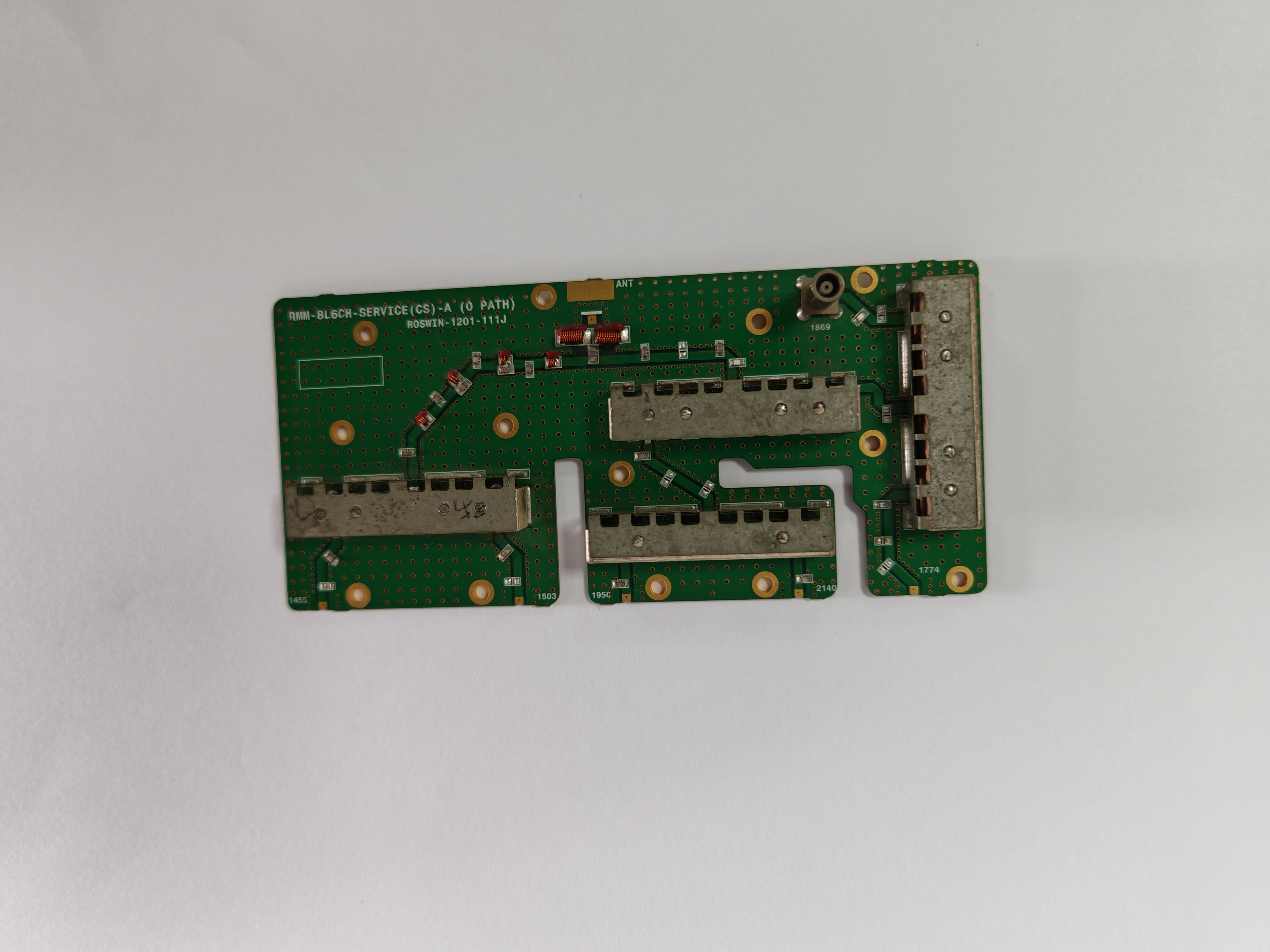
An LC filter represents one of the most fundamental and effective circuit designs in electronics, serving as a cornerstone for signal conditioning, noise reduction, and frequency management across countless applications. Whether you are designing radio frequency systems, power supplies, audio equipment, or communication networks, understanding lc filter circuits and their proper implementation directly impacts your project's performance, efficiency, and reliability. The lc filter combines inductance and capacitance in precisely calculated configurations to attenuate unwanted frequency components while allowing desired signals to pass with minimal distortion.
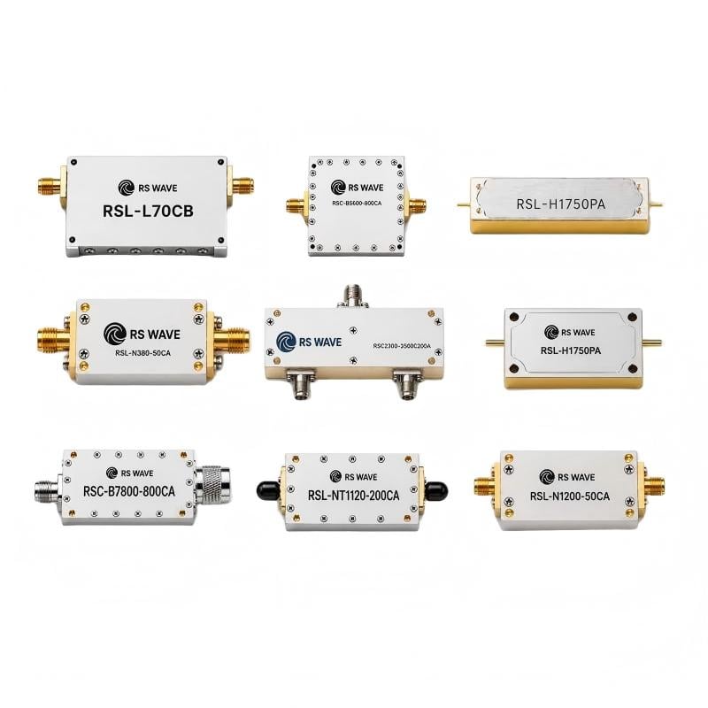
The elegance of lc filter circuits lies in their passive nature, requiring no external power supply while delivering exceptional frequency selectivity and steep roll-off characteristics. For engineers and hobbyists working on electronics projects, selecting the right lc filter configuration determines whether your system achieves clean signal transmission, reduces electromagnetic interference, protects sensitive components, or maintains signal integrity under challenging operating conditions. This comprehensive guide explores the best lc filter options, design principles, and practical implementation strategies to help you optimize your electronics projects.
Understanding LC Filter Circuit Fundamentals
Core Principles of LC Filter Design
An lc filter operates by storing energy alternately in its inductive and capacitive components, creating resonant behavior that produces selective frequency response. The lc filter's impedance characteristics change dramatically across different frequency ranges, making it ideal for separating wanted signals from unwanted noise, harmonics, or interference. By carefully tuning the inductance and capacitance values, an lc filter can be designed to have a specific cutoff frequency, quality factor, and impedance profile that matches your application requirements.
The fundamental mathematics governing lc filter performance derives from the resonant frequency formula, where the lc filter's center frequency depends on the product of inductance and capacitance values. This mathematical relationship enables precise prediction of lc filter behavior and allows engineers to calculate component values based on desired specifications. Understanding these principles ensures that your lc filter circuits will perform as designed and maintain effectiveness across your electronics projects' operating conditions.
Why LC Filter Circuits Outperform Simple Resistive Filters
Resistive filtering approaches waste power through heat dissipation and typically produce gradual roll-off characteristics, whereas lc filter circuits provide steep attenuation slopes without energy loss. The lc filter's passive implementation eliminates noise contributions that would accompany active filtering stages, resulting in cleaner output signals. For bandwidth-sensitive applications and high-power electronics projects, choosing lc filter designs over resistive alternatives significantly improves system efficiency and signal quality.
Common LC Filter Circuit Configurations for Electronics Projects
Series and Parallel LC Filter Arrangements
The series lc filter configuration places inductance in series with the signal path while capacitance connects to ground, creating a low-pass characteristic that strongly attenuates high frequencies. This arrangement of lc filter circuits works exceptionally well for power supply filtering, where the series inductor blocks high-frequency switching noise while the shunt capacitor absorbs conducted interference. Conversely, a parallel lc filter arrangement reverses component placement, producing different impedance characteristics suited to specific frequency management objectives in electronics projects.
Combining series and parallel stages creates multi-section lc filter circuits that achieve even steeper roll-off slopes and improved performance across broader frequency ranges. The lc filter's effectiveness scales with the number of stages, allowing you to match component complexity to your electronics projects' performance demands. Determining whether to use single-stage or multi-section lc filter configurations depends on your required attenuation depth, available space, and cost constraints.
T-Section and Pi-Section LC Filter Implementations
T-section lc filter designs employ two series inductors flanking a shunt capacitor, providing excellent impedance matching characteristics and controlled frequency response across electronics projects. The T-section lc filter configuration delivers a more symmetrical filter characteristic and improved performance when connected to mismatched impedance sources or loads. Pi-section lc filter arrangements reverse this geometry, using two shunt capacitors with a series inductor between them, excelling at applications requiring high current handling or specific impedance profiles.
Selecting between T-section and pi-section lc filter topologies involves analyzing your electronics projects' impedance requirements, desired attenuation characteristics, and component tolerance considerations. The lc filter's topology directly influences its impedance matching capability, insertion loss, and frequency response shape, making topology selection a critical design decision for successful project implementation.
Practical Applications and Selection Criteria
Radio Frequency and Communication Applications
Radio frequency systems depend critically on lc filter circuits to suppress spurious emissions, reject adjacent channel interference, and ensure compliance with regulatory frequency masks. The lc filter circuits in RF applications must handle high power levels, maintain low insertion loss, and provide precise frequency selectivity across the operating band. For communication electronics projects, lc filter designs separate transmitted and received signals, protect sensitive input stages from strong interfering signals, and maintain system dynamic range.
Modern wireless and cellular systems extensively employ tuned lc filter circuits as part of their signal conditioning architecture, where the lc filter's passive nature and temperature stability provide reliable performance across varying environmental conditions. Understanding RF-specific lc filter design constraints, including Q-factor optimization, impedance matching, and power handling limits, ensures your electronics projects achieve commercial-grade performance and regulatory compliance.
Power Supply and DC Filtering Applications
Power supply circuits rely on lc filter stages to reduce switching noise, attenuate conducted emissions, and prevent harmful harmonic currents from returning to the power grid. The lc filter in power supply applications must handle significant current levels while maintaining low DC resistance and preventing core saturation. Properly designed lc filter circuits in switching power supplies dramatically reduce conducted EMI, allowing smaller shielding and cable requirements while improving overall system reliability.
Audio and precision measurement electronics projects benefit from lc filter circuits that provide extremely low noise floors without introducing phase distortion across the signal bandwidth. The lc filter's ability to reject specific frequency bands without broadband attenuation makes it superior to resistive approaches for applications where signal preservation and bandwidth efficiency matter critically.
Key Selection Criteria for Your Electronics Projects
When choosing an lc filter configuration for your electronics projects, prioritize frequency range requirements, desired attenuation depth, impedance matching needs, physical space constraints, and cost considerations. The lc filter's performance envelope, determined by component tolerances and operating temperature range, must accommodate your application's entire operating spectrum. Evaluating whether your lc filter must handle high power levels, operate across wide temperature ranges, or maintain performance under varying load impedances helps eliminate unsuitable lc filter configurations early in your design process.
Component quality significantly impacts lc filter performance, particularly for high-Q applications where inductor losses and capacitor dielectric characteristics directly influence the lc filter's effective bandwidth and insertion loss. Selecting lc filter components from reputable manufacturers with documented specifications and temperature stability ratings ensures your electronics projects achieve design targets consistently throughout their operational lifetime.
FAQ
What frequency range should my lc filter cover?
Your lc filter frequency range depends entirely on your application requirements: identify the highest undesired frequency you must attenuate and the lowest signal frequency that must pass without significant attenuation, then design your lc filter's cutoff frequency between these boundaries. For power supply applications, lc filter frequency ranges typically span from switching frequency harmonics upward, while RF applications require lc filter circuits tailored to specific communication bands. Calculating the lc filter's required component values involves working backward from your specified frequency range using standard filter design equations.
How do I calculate component values for an lc filter?
Component value calculation for an lc filter begins with determining your desired cutoff frequency, characteristic impedance, and filter order, then applying standard filter design tables or equations to calculate inductance and capacitance values. The lc filter's resonant frequency formula (f = 1/2π√LC) provides the mathematical foundation for quick prototyping calculations, while more detailed design procedures account for source impedance, load impedance, and desired filter shape. Many design software tools and online calculators exist specifically for lc filter design, dramatically reducing manual calculation time while improving accuracy for complex lc filter topologies.
Can I use a single LC filter stage or do I need multiple stages?
Single-stage lc filter circuits provide reasonable performance for many applications, achieving approximately 40 dB per decade roll-off slope, but applications requiring steeper attenuation or broader frequency ranges typically benefit from multi-stage lc filter configurations. Adding additional lc filter stages increases roll-off slope, improves stop-band attenuation, and extends useful filtering bandwidth, but increases component count, cost, and physical size. Your required attenuation depth, available frequency margin, and component tolerance budget determine whether your electronics projects need single or multiple lc filter stages to meet specifications.