
 EN
EN
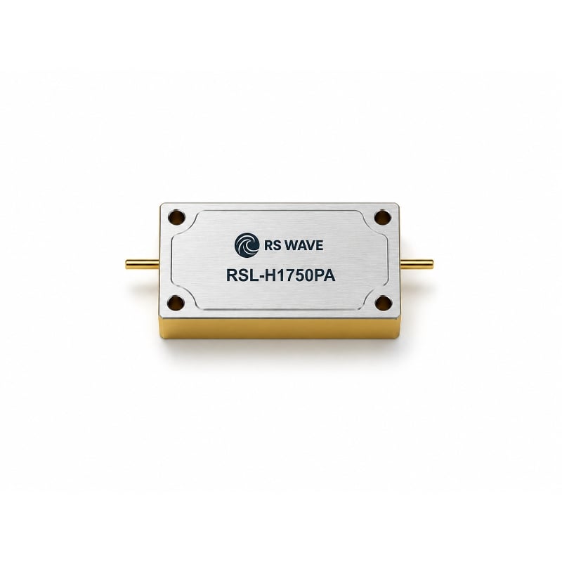
Low Earth Orbit (LEO) satellites are changing the way broadband, positioning, remote sensing, and IoT services are delivered. Compared with traditional geostationary satellites, LEO spacecraft fly much closer to the Earth, which can reduce link distance and make large satellite constellations practical for global coverage. But this architecture also creates a demanding RF environment. A LEO satellite moves rapidly across the sky, hands traffic from beam to beam, operates near other spacecraft and terrestrial networks, and must keep every gram, watt, and cubic centimeter under control. In this environment, the RF filter is not a small supporting part. It is one of the core devices that protects signal quality from the antenna to the modem.
An RF filter selects the useful frequency band and rejects unwanted energy outside that band. In a satellite communication link, the antenna receives more than the desired signal. It may also capture adjacent-channel emissions, harmonics from onboard electronics, leakage from transmit paths, 5G and Wi-Fi interference near ground terminals, and noise from power systems. Without proper filtering, these unwanted signals can reduce receiver sensitivity, create intermodulation products, or even overload low-noise amplifier stages. For LEO networks, where coverage, throughput, and handover reliability all depend on stable RF performance, the filter directly affects the quality of service.
Why LEO Satellite RF Front Ends Need Better Filtering
LEO satellites and their terminals usually operate with tight link budgets. Every decibel of insertion loss before the first low-noise amplifier can reduce the effective sensitivity of the receiver. At the same time, insufficient out-of-band rejection can let powerful unwanted signals enter the receive chain. The design target is therefore a careful balance: low insertion loss in the passband, steep rejection outside the passband, stable center frequency, compact size, and repeatable performance over temperature.
This is where microwave dielectric ceramic filters, LC filters, cavity filters, and duplexers become highly relevant. Jiaxing Ruishang Electronic Technology Co., Ltd. focuses on microwave ceramic components, including ceramic filters, duplexers, LC filters, cavity filters, ceramic antennas, and GNSS positioning antennas. Its product frequency coverage reaches DC–30 GHz, and the company provides customized designs for RF circuits, UAVs, radar, electronic countermeasures, navigation, signal amplifiers, surveying, and related RF applications. These capabilities match the component-level requirements found in satellite communication terminals, ground stations, navigation receivers, and RF payload support systems.
Microwave Dielectric Ceramic Filters for Compact Payloads
Microwave dielectric ceramic filters use high dielectric constant, low-loss, temperature-stable ceramic materials as resonators. Their main advantage is miniaturization: a high dielectric constant shortens the electromagnetic wavelength inside the material, allowing smaller resonant structures than many traditional air-cavity designs. For LEO satellites, where payload space and mass are limited, this compactness is valuable. A smaller filter can support denser RF front-end integration, more channels in a payload, or a more compact user terminal.
RSWave’s microwave dielectric ceramic filter series highlights smaller size, lighter weight, excellent temperature stability, a 400 MHz to 7000 MHz frequency range, customization, and simulation-based design support. The product table also includes GPS/BDS, LTE, 5G, wideband, and satellite communication references, including a 7200 MHz narrowband SAT-COMM example. In LEO applications, these filters can be considered for S-band, C-band, navigation-related bands, and customized sub-7 GHz or near-7 GHz channels, depending on the full system specification.
Temperature stability is especially important. A LEO satellite experiences repeated thermal cycling as it moves between sunlight and eclipse, while outdoor ground terminals face seasonal and daily temperature variation. If a filter’s resonant frequency drifts too far, the passband can move away from the assigned channel, causing loss of wanted signal or weaker rejection of adjacent energy. Temperature-stable ceramic materials help maintain predictable RF behavior across these operating conditions.
LC and Cavity Filters in LEO Ground Terminals and Gateways
Different LEO systems need different filter structures. RF LC filters, built from inductors and capacitors, are often used where compact size, cost efficiency, and integration flexibility matter. They can be designed as low-pass, high-pass, band-pass, or band-stop filters. In a terminal or gateway RF board, LC filters may remove harmonics after frequency conversion, suppress spurious emissions, or provide intermediate-frequency channel selection.
Cavity filters serve another role. Because they use metal resonant cavities and high-Q resonators, they can provide strong out-of-band rejection, low insertion loss, and good power handling. This makes them suitable for gateways, high-power RF terminals, radar links, and ground infrastructure where performance is more important than the smallest possible footprint. RSWave’s RF LC Filter & Cavity Filter product line covers DC to 30 GHz, supports compact forms such as surface-mount and through-hole options, and is described for satellite communication terminals, military communication terminals, radar equipment, and aerospace RF modules.
In practical LEO networks, the ground segment is just as important as the spacecraft. Gateways must handle high traffic density, track fast-moving satellites, and maintain clean uplink and downlink channels. A well-designed filter chain can reduce adjacent-channel interference, improve transmitter spectral purity, and protect receiver paths from high-level nearby transmitters.
Duplexers for Shared-Antenna Satellite Communication Paths
A duplexer allows a transmitter and receiver to share one antenna while keeping the transmit and receive bands isolated. This is critical in frequency-division duplex systems, where transmission and reception occur at different frequencies at the same time. In a LEO terminal, a duplexer can help reduce antenna count and simplify the RF layout. In a compact onboard or mobile system, fewer antennas and shorter RF paths can also reduce weight and integration complexity.
RSWave’s microwave dielectric ceramic duplexers use high-Q, low-loss ceramic resonators to integrate transmit and receive filtering channels. The company highlights low loss, smaller size and lighter weight, temperature stability, surface-mount suitability, a 400 MHz to 6000 MHz frequency range, and customization. Its product description notes that ceramic duplexers are used in IoT terminals, industrial communication, base station equipment, portable devices, automotive electronics, and satellite navigation and communication.
For LEO designs, duplexers must do more than separate two channels. They must protect the low-noise receiver from transmitter leakage, maintain isolation during rapid signal changes, and keep insertion loss low enough to preserve link margin. High isolation is also important because the receiver is often trying to detect weak downlink signals while the transmitter may be operating at a much higher power level.
Key Design Considerations for Engineers
When choosing an RF filter for a LEO satellite-related system, engineers should start with the frequency plan. The center frequency, bandwidth, channel spacing, guard band, and regulatory mask define the filter response. Next comes insertion loss. A low-loss filter improves the receive noise figure and reduces transmitter power waste. Rejection is equally important, especially near strong adjacent services or in multi-band terminals. VSWR affects impedance matching and total RF chain efficiency, while ripple affects signal flatness across wideband channels.
Mechanical and environmental requirements must also be considered. For onboard spacecraft hardware, radiation tolerance, vibration, shock, outgassing, thermal-vacuum performance, and mission-level screening must be validated separately. For ground terminals and gateways, designers may prioritize weather resistance, connector type, production repeatability, and long-term temperature stability. In both cases, custom filter design can be essential because LEO systems often use non-standard bandwidths or tightly packed frequency plans.
The Value of Customized RF Filtering
LEO satellite communication is not a one-size-fits-all market. A broadband user terminal, a gateway station, a TT&C link, a GNSS-enhanced navigation receiver, and an RF sensing payload may all require different filtering architectures. RSWave’s emphasis on customized specifications and simulation design support is therefore important. Instead of forcing the RF chain around a generic component, engineers can tune the filter around system-level goals such as passband flatness, rejection depth, footprint, connector layout, and cost.
As LEO constellations expand, RF front-end components will continue to determine how reliably terminals connect, how cleanly payloads transmit, and how efficiently spectrum is used. Ceramic filters, LC filters, cavity filters, and duplexers each offer a different balance of size, loss, rejection, power handling, and integration. Used correctly, they help LEO satellite systems deliver stable links in a crowded RF environment.
For companies developing satellite communication terminals, ground stations, navigation modules, radar-related RF systems, or customized microwave front ends, RF filtering should be treated as an early design decision rather than a final board-level detail. The right filter architecture can improve link margin, reduce interference, simplify integration, and support reliable operation from the laboratory to the field.
Table of Contents
- Why LEO Satellite RF Front Ends Need Better Filtering
- Microwave Dielectric Ceramic Filters for Compact Payloads
- LC and Cavity Filters in LEO Ground Terminals and Gateways
- Duplexers for Shared-Antenna Satellite Communication Paths
- Key Design Considerations for Engineers
- The Value of Customized RF Filtering