
 EN
EN
Satellite communication links operate across enormous distances, yet many critical performance decisions are made inside a compact RF front end. Antennas, low-noise amplifiers, power amplifiers, and frequency converters usually receive much of the attention, but the RF filter determines which parts of the spectrum can move through the signal chain and which should be rejected.
That function is becoming increasingly important as satellite networks, terrestrial wireless systems, radar, navigation, and broadband services operate in neighboring spectrum. In practical hardware, an RF filter is not simply a “noise remover.” It protects receiver sensitivity, limits unwanted transmitter energy, controls interference, and supports stable operation across the RF architecture.
Why Satellite Links Need Precise Frequency Control
A satellite receiver often has to recover an extremely weak wanted signal while much stronger signals may exist nearby in frequency. If those unwanted signals enter the RF front end with insufficient attenuation, they can reduce effective receiver sensitivity or drive low-noise amplifiers and mixers toward compression.
ESA documentation for satellite command receivers describes extensive filtering throughout the RF and IF chain. It also gives an example of an input waveguide band-pass cavity filter being used to prevent far out-of-band interference from saturating LNAs and RF mixers.
The useful passband must therefore remain low loss, while the stopbands need enough rejection to prevent strong blockers, harmonics, and spurious responses from reaching sensitive stages.
There is also an important engineering tradeoff. More filtering is not automatically better. ITU-R technical guidance for fixed-satellite-service earth stations points out that introducing a filter into the receive path also introduces insertion loss, which can reduce receive-chain gain and increase system noise temperature. The real objective is therefore strong frequency selectivity with the lowest practical insertion loss, rather than simply maximizing attenuation.
The RF Filter as the Receiver’s First Line of Defense
In a typical satellite terminal, filtering can appear before or after the LNA, around frequency mixers, and in intermediate-frequency stages. A preselection filter positioned near the antenna narrows the spectrum reaching the first active device. This is especially valuable where satellite earth stations coexist with cellular networks, microwave links, radar, or other high-power RF sources.
A properly designed band-pass filter preserves the required communication channel while suppressing frequencies outside the assigned band. For a narrowband receiver, the transition-band requirement can be particularly demanding because a strong interfering signal may be located close to the wanted signal.
The filter must therefore balance several parameters, including skirt selectivity, insertion loss, bandwidth, impedance matching, group-delay behavior, and physical dimensions.
At later stages of the receiver, additional LC, ceramic, or cavity filters can refine channel selection and remove unwanted mixer products. The exact topology depends on the terminal’s frequency plan and RF architecture. For that reason, filtering is best treated as part of the overall receiver design rather than as an isolated catalog component.
Filters Also Keep the Transmitter Clean
RF filters are equally important on the transmit side.Power amplifiers can generate harmonics and other unwanted spectral components, while synthesizers and frequency-conversion stages may introduce spurious responses. A suitable low-pass, band-pass, or cavity filter suppresses this unwanted energy before it reaches the antenna.
Filtering also becomes important when transmitting and receiving circuitry are physically close to each other. Insufficient isolation may raise the local noise floor or desensitize the receiving path.
For shared-antenna systems, duplexers and diplexers extend this frequency-selective function by separating transmit and receive bands. Their insertion loss, isolation, and power-handling characteristics become part of the complete RF link budget.
In other words, filtering is not merely an accessory installed after the RF architecture has already been defined. It is a frequency-management layer that helps the entire satellite terminal operate predictably.
Choosing Between LC, Cavity, and Dielectric Ceramic Filters
There is no single RF filter technology that is ideal for every satellite communication system. The correct choice depends on operating frequency, bandwidth, power level, allowable insertion loss, available space, rejection requirements, and environmental conditions.
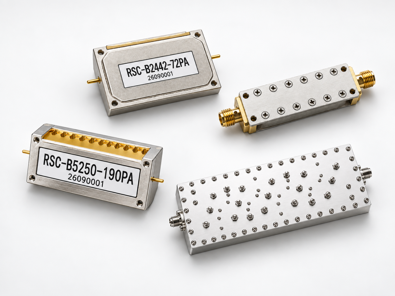
LC filters are useful when engineers need flexible low-pass, high-pass, band-pass, or band-stop responses together with straightforward circuit integration. RSWave's RF LC and cavity filter portfolio covers a broad range extending up to 30 GHz and includes different package and integration options. The company specifically identifies satellite communication terminals and aerospace RF modules among the relevant applications for its LC filter solutions.
Cavity filters are frequently considered when low insertion loss, high Q, strong out-of-band rejection, and higher power handling are important. Their metallic resonant structures can provide steep frequency discrimination, although cavity solutions may require more physical volume than highly miniaturized alternatives
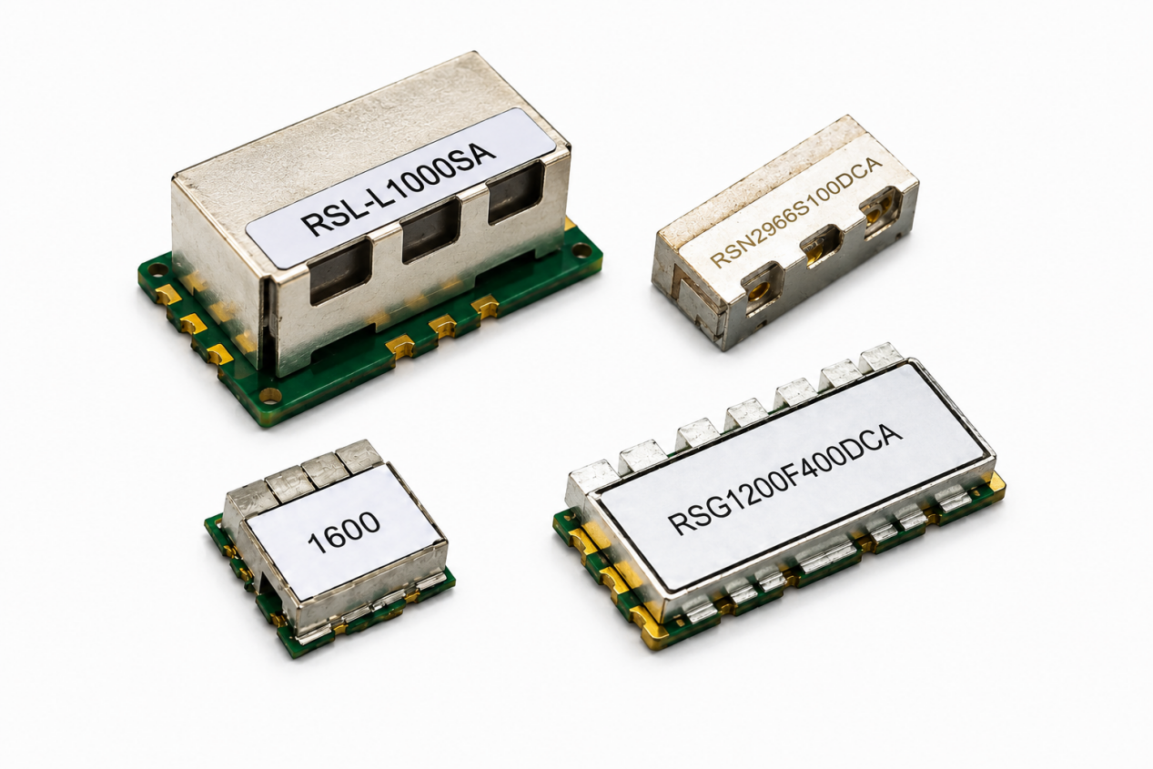
Microwave dielectric ceramic filters provide another useful balance. High-dielectric-constant resonator materials allow the physical size of the filtering structure to be reduced while maintaining microwave-frequency selectivity and temperature stability.
RSWave describes its dielectric ceramic filter range as suitable for applications including satellite communications, radar, T/R modules, and other RF front ends. The product page summarizes the family in the 400 MHz to 7 GHz range, while its technical table also includes an application-specific satellite-communication example centered at 7.2 GHz. For an engineering program, exact frequency capability should therefore be confirmed against the required specification and customized design.
A practical satellite RF system may use more than one filtering technology. A cavity filter, for example, may serve a high-power or high-selectivity stage, while a compact ceramic or LC filter is used deeper inside the module where PCB space and integration are more important.
A Concrete Satellite-Communication Filter Example
Product selection becomes more meaningful when it is tied to measurable RF specifications instead of generic performance claims.
In RSWave's microwave dielectric ceramic filter table, the RMP4A7200S10FCA is identified for a “SATE-COMM” application. It is listed with a center frequency of 7.2 GHz, a 10 MHz bandwidth, maximum insertion loss of 3.0 dB, maximum ripple of 1.0 dB, maximum VSWR of 1.5, and minimum attenuation of 30 dB across 5.0–6.2 GHz.
These figures illustrate the types of parameters an RF engineer should examine before integrating a filter.
Center frequency and bandwidth determine what spectrum must pass. Insertion loss directly affects available link margin. Stopband rejection shows how strongly unwanted energy can be suppressed. VSWR indicates the quality of impedance matching and influences how efficiently RF power is transferred between connected stages.
The RSWave catalog also indicates that other operating frequencies can be customized. This flexibility is particularly relevant to satellite communications because terminals rarely share one universal frequency plan. A filter may need to be optimized around a specific transponder, intermediate-frequency architecture, regional allocation, channel bandwidth, interference environment, or mechanical enclosure.
What Engineers Should Evaluate Before Specifying an RF Filter
For satellite communication hardware, an effective filter design process begins with the system requirements rather than the filter technology itself:
- Exact passband: Define the operating frequency, occupied bandwidth, and sufficient margin for frequency drift and manufacturing tolerance.
- Real blocker frequencies: Stopband attenuation should be specified at frequencies where interfering signals are realistically expected.
- Allowable insertion loss: A filter positioned before the LNA can have a greater effect on receiver noise performance than a filter located later in the signal chain.
- Power handling: Transmit-path filters require different thermal and breakdown considerations from small-signal receive filters.
- Temperature stability: Outdoor earth stations, aerospace equipment, and mobile satellite terminals can experience significant environmental variation.
- Mechanical integration: Connectorized, surface-mount, and through-hole formats create different requirements for PCB layout, grounding, shielding, and maintenance.
- Customization requirements: In crowded RF environments, a standard filter may not provide the transition bandwidth or rejection points required by the system.
These requirements also demonstrate why engineering support can be as important as the physical component itself.
Jiaxing Ruishang Electronic Technology Co., Ltd. states that it has been engaged in microwave ceramic component R&D, manufacturing, and sales since 2015. Its current portfolio includes ceramic filters, duplexers, LC filters, cavity filters, ceramic antennas, and GNSS antenna products, with the broader product range covering frequencies up to 30 GHz.
For satellite terminal designers, the practical advantage of a diversified RF component portfolio is the ability to match different filtering structures to different positions in the signal chain instead of forcing a single technology to satisfy every requirement.
From Component Selection to End-to-End RF Integrity
Modern satellite communication is moving toward higher throughput, smaller terminals, and denser spectrum utilization. These trends place additional pressure on RF front ends: more bands need to coexist, antennas are becoming increasingly integrated, and receivers still need to detect weak signals in the presence of strong nearby transmissions.
The RF filter therefore performs a system-level function.
It protects sensitive active circuitry, controls spectral occupancy, reduces out-of-band interference, and helps preserve the signal-to-noise performance required by the modem and baseband processor. Its influence can ultimately be seen in receiver dynamic range, transmitter spectral performance, adjacent-band coexistence, and overall communication reliability.
For satellite terminal engineers, the most effective approach is to treat filtering as an early architectural decision. Define the frequency plan, blocker environment, allowable loss, power level, temperature range, and mechanical constraints first. Then select an LC, cavity, dielectric ceramic, or combined filtering solution capable of meeting those requirements.
Conclusion
RF filters are among the least visible but most consequential components in a satellite communication system. Their role goes far beyond simply “cleaning” a signal. They determine how effectively the RF chain separates useful energy from interference while preserving the limited link margin available across long-distance satellite paths.
With LC filters, cavity filters, microwave dielectric ceramic filters, and duplexing solutions available for different frequency, size, selectivity, and power requirements, engineers can build a filtering strategy around the actual needs of the satellite terminal.
For applications requiring custom center frequencies, bandwidths, rejection points, or package formats, combining electromagnetic simulation, filter design expertise, and customized manufacturing can help shorten the path from an RF specification to a stable and manufacturable satellite communication front end.
Table of Contents
- Why Satellite Links Need Precise Frequency Control
- The RF Filter as the Receiver’s First Line of Defense
- Filters Also Keep the Transmitter Clean
- Choosing Between LC, Cavity, and Dielectric Ceramic Filters
- A Concrete Satellite-Communication Filter Example
- What Engineers Should Evaluate Before Specifying an RF Filter
- From Component Selection to End-to-End RF Integrity
- Conclusion