
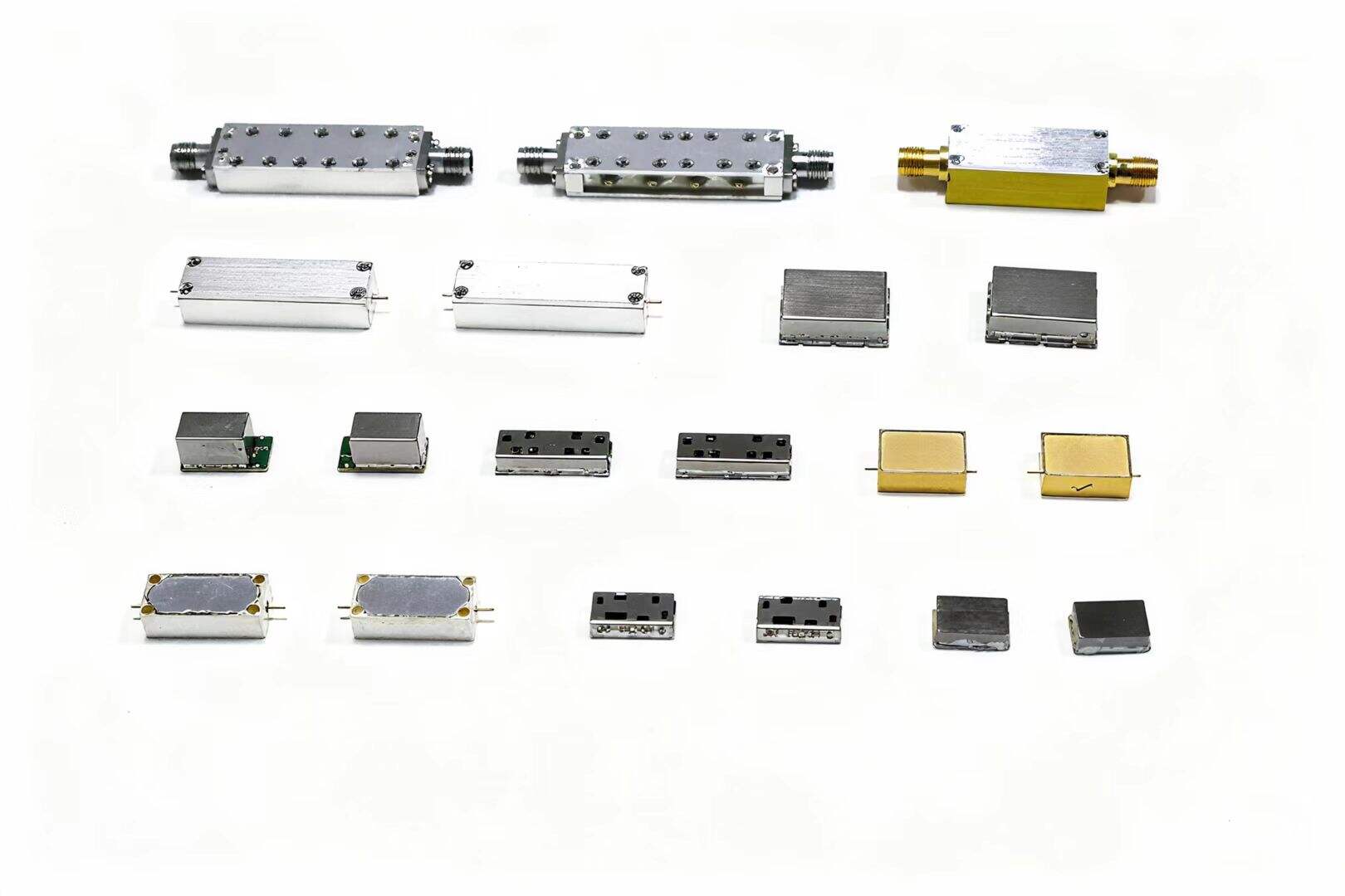
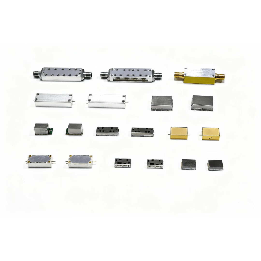
Electronic engineers frequently encounter challenges when designing and implementing filtering circuits, particularly with passive components that form the backbone of signal processing systems. An lc low-pass filter represents one of the most fundamental yet critical elements in electronic design, serving to eliminate unwanted high-frequency noise while preserving essential signal integrity. These circuits, composed of inductors and capacitors arranged in specific configurations, play vital roles in power supplies, audio equipment, communication systems, and countless other applications where clean signal transmission is paramount.
Understanding LC Low-Pass Filter Fundamentals
Basic Circuit Configuration and Operation
The fundamental structure of an lc low-pass filter consists of an inductor connected in series with the signal path and a capacitor connected in parallel to ground. This arrangement creates a frequency-dependent impedance network that naturally attenuates high-frequency components while allowing low-frequency signals to pass through with minimal loss. The inductor presents increasing impedance as frequency rises, while the capacitor provides a decreasing impedance path to ground for higher frequencies.
The cutoff frequency of an lc low-pass filter is determined by the values of the inductance and capacitance according to the formula fc = 1/(2π√LC). This relationship establishes the point where the output power drops to half of the input power, corresponding to a -3dB attenuation. Beyond this frequency, the filter provides increasingly steep attenuation, typically achieving -40dB per decade in ideal conditions.
Frequency Response Characteristics
The frequency response of an lc low-pass filter exhibits distinct regions of operation that engineers must understand for proper implementation. In the passband region, frequencies below the cutoff point experience minimal attenuation and phase shift, maintaining signal integrity for desired frequency components. The transition region, centered around the cutoff frequency, demonstrates the filter's roll-off characteristics and determines how sharply the filter separates wanted from unwanted frequencies.
In the stopband region, high-frequency components experience significant attenuation, with the theoretical slope reaching -40dB per decade for a second-order LC filter. However, real-world performance often deviates from ideal behavior due to parasitic effects, component tolerances, and circuit layout considerations that introduce additional complexity to the frequency response.
Common Design and Implementation Problems
Component Value Selection Issues
One of the most frequent problems encountered with lc low-pass filter designs involves improper component value selection that fails to achieve the desired cutoff frequency or attenuation characteristics. Engineers often struggle with balancing the inductor and capacitor values to meet both frequency response requirements and practical implementation constraints such as component size, cost, and availability.
Tolerance stacking represents another significant challenge, where the combined effects of component tolerances can shift the actual cutoff frequency substantially from the calculated design value. Standard capacitors and inductors typically have tolerances ranging from 5% to 20%, and when combined, these variations can result in cutoff frequency deviations of 30% or more from the intended design specification.
Parasitic Effects and Non-Ideal Behavior
Real-world inductors and capacitors exhibit parasitic properties that significantly impact lc low-pass filter performance beyond the ideal theoretical predictions. Inductors possess inherent series resistance, parallel capacitance, and core losses that affect both the frequency response and the quality factor of the filter. These parasitic elements can create unwanted resonances, reduce attenuation effectiveness, and introduce additional phase distortion.
Capacitors similarly exhibit parasitic inductance and equivalent series resistance that become increasingly problematic at higher frequencies. The parasitic inductance of capacitors can cause the component to behave inductively above its self-resonant frequency, potentially creating unwanted peaks in the filter response and degrading the intended low-pass characteristics.
Impedance Matching and Loading Effects
Source and Load Impedance Considerations
Proper impedance matching represents a critical aspect of successful lc low-pass filter implementation that is often overlooked during the design phase. The filter's performance heavily depends on the source and load impedances connected to its input and output terminals. Mismatched impedances can cause reflections, alter the effective cutoff frequency, and degrade the filter's attenuation characteristics.
When an lc low-pass filter is connected between impedances that differ significantly from the design values, the actual frequency response can vary dramatically from the intended performance. This impedance sensitivity requires careful consideration of the complete signal chain, including the driving circuit's output impedance and the load circuit's input impedance.
Termination and Interface Problems
Improper termination techniques frequently lead to performance degradation in lc low-pass filter implementations. The physical connection methods, trace impedances, and ground return paths all contribute to the overall filter performance and can introduce unwanted parasitic effects that compromise the design objectives.
Ground loops and inadequate grounding schemes represent particularly troublesome issues that can inject noise, create instability, and reduce the effective common-mode rejection of the filter circuit. These problems become more pronounced at higher frequencies where even small inductances and capacitances in the ground system can significantly impact performance.
Practical Solutions and Design Improvements
Component Selection Strategies
Addressing component-related issues requires a systematic approach to inductor and capacitor selection that considers both electrical and physical characteristics. High-quality components with tighter tolerances, such as precision capacitors with 1% or 2% tolerance ratings, can significantly improve the predictability and consistency of filter performance across production units.
For inductors, selecting components with high quality factors and appropriate current handling capabilities ensures stable operation and minimizes losses. Air-core inductors offer excellent linearity and minimal core losses but require larger physical sizes, while ferrite-core inductors provide higher inductance values in smaller packages but may introduce nonlinear effects under high current conditions.
Layout and Construction Techniques
Proper printed circuit board layout techniques play a crucial role in achieving optimal lc low-pass filter performance. Component placement should minimize parasitic coupling between input and output circuits, with adequate spacing and proper grounding to prevent unwanted feedback paths that can degrade attenuation performance.
Ground plane design requires special attention, with solid, low-impedance ground returns for both the inductor and capacitor connections. Star grounding techniques can help minimize ground loop formation, while careful trace routing ensures that parasitic inductances and capacitances do not significantly alter the intended filter characteristics.
Advanced Troubleshooting Methods
Measurement and Characterization Techniques
Effective troubleshooting of lc low-pass filter problems requires appropriate measurement equipment and techniques to accurately characterize the filter's actual performance versus design specifications. Network analyzers provide the most comprehensive frequency response measurements, allowing engineers to identify specific frequency ranges where performance deviates from expectations.
Time-domain measurements using oscilloscopes can reveal transient behavior and settling characteristics that frequency-domain measurements might not fully capture. Step response and pulse response measurements help identify overshoot, ringing, or damping issues that could indicate component quality problems or parasitic effects.
Simulation and Modeling Approaches
Modern circuit simulation tools enable engineers to model parasitic effects and non-ideal component behavior before physical implementation, potentially identifying problems during the design phase. SPICE-based simulators can incorporate detailed component models that account for parasitic resistances, inductances, and capacitances to provide more realistic performance predictions.
Monte Carlo analysis capabilities allow designers to evaluate the effects of component tolerances and manufacturing variations on filter performance, enabling robust design approaches that maintain acceptable performance across the expected range of component variations.
FAQ
What causes an LC low-pass filter to have poor attenuation performance
Poor attenuation performance typically results from parasitic effects in real components, impedance mismatches, or inadequate component quality factors. Inductors with high series resistance and capacitors with significant equivalent series resistance can reduce the effective Q of the filter, leading to gentler roll-off characteristics. Additionally, improper grounding or layout can create parasitic feedback paths that compromise attenuation effectiveness.
How do component tolerances affect LC filter cutoff frequency accuracy
Component tolerances directly impact cutoff frequency accuracy through the square root relationship in the LC formula. When both inductor and capacitor values vary within their tolerance ranges, the combined effect on cutoff frequency can be substantial. For example, if both components have 10% tolerances and vary in opposite directions, the cutoff frequency could shift by approximately 20% from the nominal design value.
Why does my LC filter show unexpected resonant peaks in the response
Unexpected resonant peaks usually indicate parasitic effects from component self-resonances or layout-induced parasitics. Capacitors have parasitic series inductance that creates self-resonance above their intended operating frequency, while inductors exhibit parasitic parallel capacitance. Poor PCB layout can also introduce unwanted coupling between filter elements or create resonant circuits with trace inductances and capacitances.
What is the best approach for impedance matching LC filters
The best approach involves designing the filter for the actual source and load impedances rather than assuming standard values. This may require using impedance transformation techniques or buffer amplifiers to present the correct impedances to the filter. Alternatively, consider using multiple filter sections with appropriate interstage matching, or employ active filter topologies that can provide better impedance isolation between stages.